
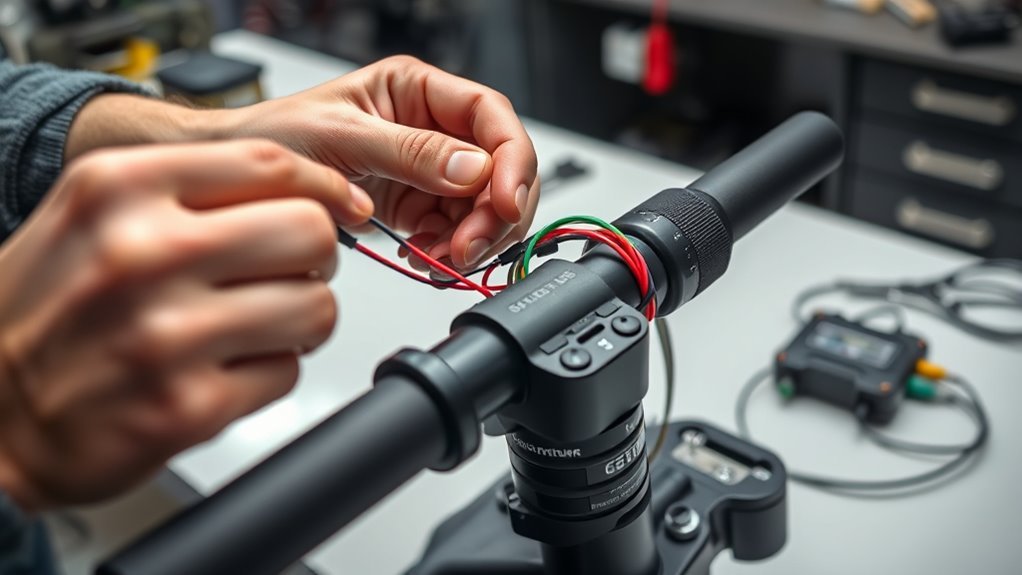
Last Updated on September 10, 2026 by Daniel Globe
Electric scooter throttle wiring looks simple when a throttle has only three wires, but the wire colors and voltage ranges are not standardized across every scooter or controller. A typical Hall-effect throttle needs a low-voltage supply, ground, and a variable signal, but you should identify those functions from the exact controller diagram or connector pinout before making any connection.
Quick Answer
A three-wire Hall throttle normally uses a low-voltage supply, ground, and signal wire, but there is no universal scooter wire-color standard. Verify the exact controller pinout first. Many Hall throttles produce a signal somewhere around 1–4 volts, but the correct supply and signal range depends on the controller.
Key Takeaways
- Treat red, black, green, white, blue, yellow, and brown wire colors as clues, not universal standards.
- Find the scooter or controller’s wiring diagram and identify the throttle connector by pin and function before connecting wires.
- A Hall throttle commonly has supply, ground, and variable signal conductors, but its exact voltage range is controller-specific.
- Disconnect the battery before unplugging, repinning, splicing, soldering, or performing resistance or continuity tests.
- Never apply full battery voltage to an ignition, key, or throttle wire merely because its color matches a generic diagram.
- Stop and use a qualified technician if the connector carries unknown battery voltage, the battery or wiring is damaged, or the scooter moves unexpectedly during testing.
At a Glance
| Time Required | About 20–45 minutes for inspection and basic low-voltage diagnosis; longer if the scooter must be disassembled. |
| Difficulty | Intermediate. Model-specific electrical knowledge is required. |
| Tools Needed | Manufacturer wiring diagram, digital multimeter, insulated probes or back-probes, basic hand tools, and suitable connector-insulation materials. |
| Cost | Usually little or no cost for diagnosis if you already own a multimeter; replacement throttle or controller cost varies by model. |
Warning: An electric scooter contains a propulsion system and a high-energy battery. Disconnect battery power before modifying connectors or wiring. Do not probe an unknown high-voltage harness, open a lithium-ion battery pack, or apply battery voltage to a throttle/key wire based on color alone. If you cannot positively identify the circuit from the manufacturer’s documentation, use a qualified repair technician.
Disclosure: As an Amazon Associate I earn from qualifying purchases. Some links on this page are affiliate links, at no extra cost to you.
Throttle Wire Color Basics
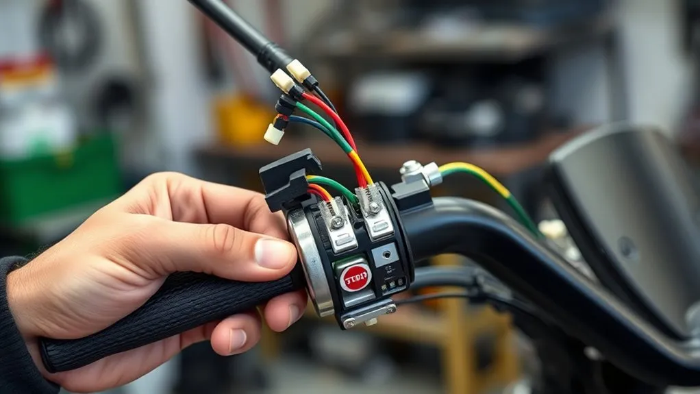
Many basic Hall-effect throttles use three conductors: a low-voltage supply, ground, and a variable signal output. Red is commonly used for the supply and black for ground, while green, white, or another color may carry the signal. However, those colors are examples rather than an industry-wide rule.
The safest approach is to identify the throttle connector in the scooter or controller’s wiring diagram and match each terminal by function and pin position. Connector orientation matters too: two connectors can use the same shell while arranging the conductors differently.
Some scooters also combine the throttle with a display, power switch, battery-voltage indicator, lighting controls, communication lines, or other functions. Those assemblies may have four, five, six, or more conductors and should not be treated as simple three-wire throttles.
Pro Tip: Photograph both sides of every connector before unplugging it. Record the connector orientation, pin positions, and wire colors. Pin position is often more useful than color when comparing the harness with a wiring diagram.
Test Throttle Wires With a Multimeter
A digital multimeter can help confirm a throttle circuit, but the test method depends on whether the scooter is powered or isolated. Use resistance or continuity mode only on an unpowered circuit. Never use those modes on an energized controller.
For an energized voltage test, first confirm from the manufacturer’s documentation that you are working on a low-voltage throttle connector. Use insulated probes or back-probe the connector without spreading or damaging the terminals. Avoid allowing the meter probe to bridge two pins.
A Hall throttle often produces a low voltage at rest and a higher voltage as the throttle is pressed or twisted, but the exact range must match the controller specification.
A useful diagnostic sequence is:
- Identify ground: Use the wiring diagram or connector pinout rather than guessing from color.
- Verify the sensor supply: Measure the documented supply pin relative to signal ground. Some systems provide about 5 V, while others may be somewhat lower.
- Measure the signal: Monitor the documented signal pin while moving the throttle slowly through its range.
- Look for a smooth change: The voltage should change predictably without sudden dropouts or unexplained spikes.
- Compare with specifications: Use the controller’s stated minimum, maximum, dead-zone, and fault limits.
For example, some controllers are designed around an approximately 1–4 V Hall-throttle input, while another controller may expect a narrower range. A reading that is normal for one controller can trigger a throttle fault on another.
Match Red, Black, and Signal Wires
If your scooter’s own diagram identifies red as the throttle supply, black as signal ground, and another conductor as the throttle signal, connect those functions exactly as specified. Do not substitute a generic red-to-red or green-to-blue rule for the manufacturer’s pinout.
Before joining anything, check:
- The controller model and revision.
- The throttle type.
- The supply voltage expected by the throttle.
- The controller’s accepted signal range.
- The connector pin order when viewed from the correct side.
- Whether the throttle assembly includes additional switches or displays.
If the replacement throttle’s colors differ from the original, wire by documented function. A correctly colored wire in the wrong connector position is still a wrong connection.
Wire the Throttle to the Controller
Once the throttle and controller pinouts are confirmed, connect supply to supply, signal ground to signal ground, and throttle signal to the controller’s documented throttle-input terminal. Keep the low-voltage control harness away from exposed battery and motor conductors, and preserve the original strain relief and connector locking mechanism.
Throttle Wire Mapping
A simple Hall throttle can be understood by function:
- Sensor supply: Powers the Hall sensor with the controller’s specified low voltage.
- Signal ground: Provides the reference used by the controller and throttle.
- Throttle signal: Changes voltage as the throttle position changes.
Do not rely on a universal color table. Manufacturers may change colors between models, suppliers, connector revisions, or replacement parts.
Controller Signal Connection
The throttle signal must reach the controller input that is specifically designated for throttle or accelerator position. Connecting it to a brake, hall-sensor, communication, lighting, or power terminal can cause a fault or damage.
Inspect the connector before assembly. Bent pins, recessed terminals, water intrusion, green or white corrosion, damaged insulation, loose crimp terminals, and stretched wires can all cause intermittent throttle behavior even when the wiring order is correct.
Connect the Ignition Wires
Some throttle assemblies include additional power-switch or ignition/key wires, but there is no universal yellow-to-red or blue-to-blue ignition wiring rule. These extra conductors may carry battery voltage, controller logic voltage, or a switched enable signal depending on the scooter and controller.
Only connect an ignition or key circuit after locating the exact terminals in the controller’s wiring diagram. Confirm the rated voltage and switching method before making the connection.
Warning: Never connect a suspected ignition wire directly to full battery voltage simply because a generic diagram shows the same color. A mistaken battery-voltage connection can damage the throttle, display, controller, or wiring and may create a short-circuit hazard.
Check Voltage Before Powering On
Before final assembly, inspect every connection with battery power disconnected. Check that terminals are fully seated, insulation is intact, connector locks engage properly, and no bare conductor can contact another pin or the frame.
If the manufacturer provides a resistance or continuity check, perform it while the system is unpowered. Do not use continuity mode on an energized controller.
If a powered low-voltage throttle test is required, verify the expected values from the service documentation first. A supply near 5 V is common on many Hall-throttle systems, but it is not universal. Likewise, the signal may rise through an approximately 1–4 V range on some systems but use different limits on others.
Note: If you see battery-pack voltage on a connector you believed was a low-voltage throttle connector, stop testing and recheck the wiring diagram before continuing.
Fix Common Throttle Wiring Mistakes
Most throttle problems are easier to diagnose when you separate wiring faults from throttle faults and controller faults.
| Symptom | Possible Cause | What to Check |
| No throttle response | No sensor supply, disconnected signal, brake interlock, controller fault | Connector seating, documented supply voltage, signal range, fault codes, brake input |
| Throttle cuts in and out | Loose terminal, broken conductor, corrosion, worn throttle | Harness movement, terminal tension, water damage, signal stability |
| Throttle fault at startup | Signal already above the controller’s accepted zero-throttle range | Resting signal voltage, throttle return action, controller settings |
| Unexpected acceleration | Incorrect pinout, damaged throttle, shorted signal, controller problem | Stop testing immediately and inspect the complete throttle circuit before riding |
If the colors do not match the expected pattern, do not force a connection. Trace the circuit using the correct documentation and connector positions.
Test the Scooter Throttle
After the wiring has been verified, check the throttle signal through its full travel. The signal should change smoothly and return consistently to its resting value when released. It should not remain high, jump unpredictably, or disappear when the handlebars or harness move.
During the first functional test after throttle or controller work, follow the manufacturer’s service procedure. Keep the scooter restrained so unexpected motor operation cannot carry the vehicle into a person or object. If the design allows an unloaded wheel test, keep the driven wheel clear of the ground and keep hands, clothing, cables, and tools away from the rotating wheel.
Stop immediately if:
- The motor starts when the throttle is untouched.
- The wheel continues driving after the throttle is released.
- The signal voltage jumps rather than changing smoothly.
- A connector becomes hot.
- You smell hot insulation or electronics.
- The controller reports a throttle or accelerator fault.
Do not road-test the scooter until the throttle reliably returns to zero and the controller shows normal behavior.
Replace the Throttle or Controller
If diagnosis points to a damaged throttle, replace it with a unit that is electrically and mechanically compatible with the controller. Matching the connector shell alone is not enough.
Confirm:
- The throttle type matches the controller input.
- The supply voltage is compatible.
- The signal range is within the controller’s accepted range.
- The connector pinout matches exactly.
- Any integrated power switch, display, or indicator is compatible.
- The throttle returns freely to its resting position.
If the controller does not provide the expected sensor supply even with the throttle disconnected, or if a known-good compatible throttle produces the same fault, the controller or another part of the scooter’s control system may need diagnosis.
Do not open, rebuild, bypass, or probe inside the lithium-ion battery pack while troubleshooting a throttle problem. Battery-system repairs should be handled by technicians with appropriate training and equipment.
Frequently Asked Questions
How does a 3-wire throttle work?
A basic three-wire Hall throttle has a sensor-supply conductor, ground, and signal output. Moving the throttle changes the signal voltage, which the controller interprets as a request for more or less motor output. The exact supply and signal range depends on the controller.
What color is the speed limiter wire on an electric scooter?
There is no universal speed-limiter wire color. Some scooters do not use a separate limiter wire at all because speed limits are managed by the controller or firmware. Use the exact model’s service documentation rather than cutting, disconnecting, or joining a wire based on color.
What color wire is used for an e-bike or scooter throttle?
Red for sensor supply and black for ground are common, and green or white is sometimes used for signal. However, manufacturers are free to use different colors or pin orders, so always verify the connector’s documented function before wiring it.
How do you check electric scooter throttle wiring?
Start with the manufacturer’s connector diagram. With power disconnected, inspect the harness and terminals. If the manufacturer permits an energized low-voltage test, measure the documented sensor supply and throttle signal with a digital multimeter and compare the readings with the controller specification.
Should an electric scooter throttle always have exactly 5 volts?
No. A nominal 5-volt sensor supply is common, but some controllers provide a somewhat different voltage. The throttle signal range also varies. Compare your measurements with the specifications for the exact controller rather than assuming 5.00 volts is mandatory.
Why does my scooter show a throttle error when it turns on?
Many controllers expect the throttle to be at or near its zero position during startup. A damaged throttle, incorrect pinout, excessive resting signal voltage, stuck mechanism, wiring short, or incompatible replacement part can trigger a startup throttle fault.
Conclusion
Correct electric scooter throttle wiring depends on identifying functions rather than trusting wire colors. A basic Hall throttle usually needs a sensor supply, ground, and variable signal, but the correct pin order and voltage range come from the specific controller documentation. Verify the harness before connecting it, isolate battery power during wiring work, and stop if you find unknown battery voltage, damaged conductors, or unexpected motor movement.
A smooth throttle signal and reliable return to zero are essential before the scooter is ridden. When the diagram is unavailable or the electrical system cannot be positively identified, professional diagnosis is safer than trial-and-error wiring.
Sources
- U.S. Consumer Product Safety Commission — Micromobility Products-Related Deaths, Injuries and Hazard Patterns 2017–2024 — supports current micromobility electrical, throttle, fire, and unexpected-operation safety context.
- U.S. Consumer Product Safety Commission — Micromobility Battery Safety guidance — recommends compatible equipment and qualified technicians for repairs.
- UL Solutions — Personal e-Mobility Evaluation, Testing and Certification — explains ANSI/CAN/UL 2272 electrical-system safety coverage for personal e-mobility devices.
- Kelly Controls — KLS-H controller specifications — documents controller-specific Hall-throttle input and sensor-supply specifications.
- Grin Technologies — Grinfineon Controller Manual Rev. 2.2 — provides an example of a controller-specific throttle supply, signal range, and connector pinout.
- Segway — KickScooter safety guidance — advises against unauthorized modification and disassembly.

