
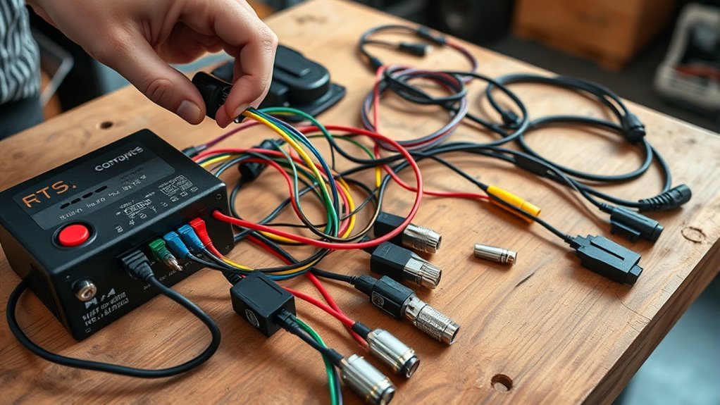
Last Updated on September 10, 2026 by Daniel Globe
Wiring an electric scooter controller safely starts with identification, not color matching. Disconnect the battery, find the controller model or wiring diagram, and identify the battery, motor phase, Hall sensor, throttle, brake, display, and power-enable connections before joining anything. Wire colors can be useful clues, but the controller and motor pinouts are the final authority.
Quick Answer
To wire an electric scooter controller, disconnect the battery first, identify every connector from the controller diagram, connect the motor phases and Hall sensors using the correct pinout, attach the throttle, brake, display, and power-enable leads, then verify battery polarity and voltage compatibility before a controlled first power-up.
Key Takeaways
- Do not assume wire colors are universal. Match the controller and motor by pinout, connector diagram, labels, or manufacturer documentation.
- Check both the battery’s nominal voltage and its maximum charged voltage against the controller’s permitted input range.
- Perform continuity and resistance tests only with the circuit de-energized. Never use continuity mode on a live battery circuit.
- Throttle, brake, display, ignition, self-learning, speed-sensor, and accessory connectors vary widely between controllers.
- For the first powered test, secure the scooter with the driven wheel off the ground and stop immediately if you see abnormal arcing, heating, smoke, or erratic motor movement.
At a Glance
| Time Required | About 30–90 minutes for an identified, compatible controller; longer if the pinout must be traced |
| Difficulty | Intermediate; advanced if connectors must be repinned or the original diagram is unavailable |
| Tools Needed | Controller wiring diagram, digital multimeter, insulated hand tools, labels, correct connectors or crimps, heat-shrink tubing, and suitable fuse protection |
| Cost | Varies; often limited to connectors, terminals, heat shrink, and fuse hardware when the battery, motor, and controller are already compatible |
Warning: A scooter battery can deliver very high current. A reversed connection, damaged wire, incorrect connector, or accidental short can cause burns, melted wiring, fire, or battery damage. Never open, bypass, rewire, or repair a lithium-ion battery pack unless you are qualified to work on battery systems. Follow the scooter, battery, and controller manufacturer’s instructions.
Disclosure: As an Amazon Associate I earn from qualifying purchases. Some links on this page are affiliate links, at no extra cost to you.
Before You Wire an Electric Scooter Controller
Start with the scooter completely powered off. Remove the key if fitted, switch the battery off if it has its own switch, and disconnect the battery from the controller. If the controller contains large capacitors, follow the manufacturer’s specified discharge procedure before testing resistance or continuity.
Next, find the model number on the controller and search for its wiring diagram or pinout. The labels printed on the controller, connector tags, and manufacturer documentation matter more than wire color. This is especially important when combining a replacement controller with a motor, display, throttle, or brake lever from another manufacturer.
Also confirm that the controller is electrically compatible with the battery and motor. Check the controller’s supported battery-voltage range, current limit, motor type, Hall-sensor support, throttle type, brake-input type, and display protocol.
A battery marked “48V” is describing a nominal voltage. A typical 13-series lithium-ion 48V-class pack may reach about 54.6V when fully charged, so the controller must tolerate the pack’s maximum charged voltage, not just its nominal label.
Pro Tip: Before unplugging an old controller, photograph every connector from several angles and label both halves of each connection. Those photos are often more useful than wire colors when installing the replacement.
Identify Electric Scooter Controller Wires
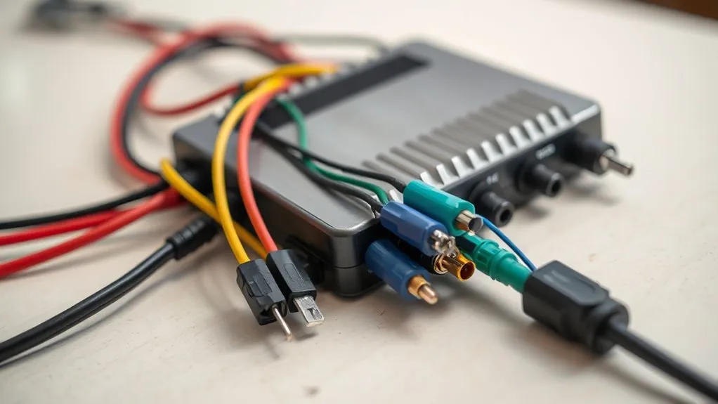
Begin by separating the high-current power wiring from the thinner signal wiring. Most brushless scooter controllers have several groups of connections, although the connector shape, color, pin count, and labeling vary.
| Wire or connector group | Common purpose | Important check |
|---|---|---|
| Battery B+ / B− | Supplies battery power to the controller | Verify polarity and permitted voltage before connection |
| Three motor phase leads | Carry switched motor current | Often yellow/green/blue, but do not rely on color alone |
| Hall sensor connector | Provides rotor-position signals on sensored motors | Usually contains sensor supply, ground, and three Hall signals |
| Throttle | Provides rider acceleration command | Confirm supply, ground, signal, and expected signal type |
| Brake cutoff / e-brake | Tells the controller that braking is requested | Can be low-level, high-level, analog, or integrated into another harness |
| Display / dashboard | Carries power, status, controls, and data | Often proprietary; matching connector shape does not guarantee compatibility |
| Ignition / lock / electric-lock lead | Enables the controller’s logic or power stage | Follow the controller diagram; never bridge unidentified wires |
| Self-learning leads | Used by some generic controllers for motor direction/phase learning | Use only when the manual specifically identifies them |
| Speed, temperature, lights, cruise, reverse, or accessories | Optional functions | Do not identify these by color alone |
Three-phase brushless motors commonly use three Hall sensors to report rotor position. A traditional separate Hall harness may contain a sensor supply, ground, and three Hall signal wires. However, modern scooters can place the three phase conductors and several sensor wires inside one waterproof multipin motor connector. Grin Technologies’ connector guide shows examples of combined connectors carrying phase, Hall, and additional sensor signals.
A white wire, orange wire, or any other single color should never automatically be identified as a speed, ignition, or learning wire. Trace it from the connector, label, schematic, or controller documentation first.
Match the Motor Phase and Hall Wires
The three thick motor phase wires carry current between the controller and the brushless motor. Yellow, green, and blue are common phase colors, but they are conventions rather than a universal guarantee.
| Connection | Typical arrangement | What matters most |
|---|---|---|
| Motor phases | Three heavy wires, often yellow/green/blue | Correct phase sequence for the specific controller and motor |
| Hall supply | Often approximately 5V on conventional Hall systems | Controller specification and motor sensor rating |
| Hall ground | Common sensor reference | Correct pin position |
| Hall A/B/C signals | Three rotor-position signal wires | Correct Hall-to-phase relationship |
If the controller and motor were designed for the same connector standard, connect them according to the documented pinout. If they came from different systems, do not assume blue-to-blue, green-to-green, and yellow-to-yellow will work. Grin’s controller documentation shows that some motor/controller combinations require different Hall mappings despite familiar wire colors.
If you see only three exposed motor leads, the motor may be sensorless, but do not conclude that immediately. The Hall wiring may use a separate hidden connector or may be incorporated into a combined motor plug. Confirm the motor specification and the controller’s sensored or sensorless capability.
Note: A wrong Hall/phase combination can make a motor shake, growl, start poorly, draw excessive current, or run in the wrong direction. Do not continue applying throttle to a motor that behaves this way.
Connect the Throttle, Brake Cutoff, and Display
Once the motor wiring is identified, connect the low-current control wiring. Start with the throttle. Many controllers use a three-wire analog throttle with a supply, ground, and signal conductor, but the exact voltage range and pin order are controller-specific. For example, some Kelly brushless controller documentation shows a 0–5V-style throttle input together with dedicated supply and ground pins. That is an example, not a universal scooter pinout.
Next, connect the brake cutoff or electronic-brake input according to the diagram. Scooter brake signals vary. Some brake levers simply switch a low-voltage input to ground, some controllers expect a higher-level input, and others use analog or proprietary electronic braking circuits. Do not assume that a black-and-white pair is always the brake connector.
Connect the display only when the controller and display are known to be compatible. A display harness can carry battery voltage, regulated power, communication data, power-switch signals, lighting control, and other functions. Two connectors that physically fit can still have different pinouts or communication protocols.
If the controller has an ignition, electric-lock, key-switch, or power-enable wire, connect it exactly as shown in the controller diagram. On some systems this lead enables the controller electronics while the main battery leads remain connected. Bridging an unidentified wire to battery positive can destroy low-voltage electronics.
Seat every connector fully without forcing pins. Repair loose terminals with the correct crimp or connector rather than twisting conductors together. Add strain relief and keep the harness away from the tire, steering movement, suspension, sharp deck edges, and brake components.
Wire the Battery to the Controller Safely
Leave the battery disconnected while preparing the controller’s main power wiring. Identify B+ and B− from the controller label or wiring diagram, then identify battery positive and negative independently. Never determine battery polarity from connector shape alone.
Battery compatibility depends on the controller’s permitted input-voltage range and the battery’s maximum charged voltage—not simply whether both are marketed as “48V.”
- Check maximum voltage. A 48V-class 13S lithium-ion battery is commonly about 54.6V when fully charged. The controller must be rated to tolerate that maximum.
- Verify polarity with a meter. If you are qualified to take a live DC measurement, set the multimeter to the correct DC-voltage range and verify the battery connector polarity without allowing the probes to bridge the terminals.
- Use suitable overcurrent protection. The fuse must have an adequate DC voltage rating and an appropriate current/interrupt rating for the battery, controller, wiring, and manufacturer’s design.
- Use properly rated connectors. Main battery connectors must tolerate the expected current and vibration. Replace heat-damaged or loose contacts rather than reusing them.
- Provide strain relief and insulation. No bare conductor should remain exposed where it could contact the scooter frame or another terminal.
Do not open the battery enclosure to bypass a battery-management system, replace cells, or attach directly to cell groups. The U.S. Consumer Product Safety Commission advises consumers to use approved batteries and charging equipment and warns against battery packs modified or reworked by unqualified personnel. CPSC’s Micromobility Information Center provides current battery and charging safety guidance.
Check Your Wiring With a Multimeter
A multimeter is useful, but the test mode matters. Separate de-energized checks from live voltage measurements.
Continuity and Resistance Tests
Disconnect the battery and follow the controller manufacturer’s discharge instructions before using resistance or continuity mode. Then check connectors, grounds, switches, and suspected broken conductors.
Warning: Never place a multimeter in resistance or continuity mode across an energized battery or powered controller. That can damage the meter and create a short-circuit hazard.
Voltage Tests
Voltage tests require the circuit to be energized and therefore involve greater risk. Use the correct DC-voltage range, insulated probes, secure test points, and steady hands. Avoid piercing insulation unless the repair procedure specifically requires it. If you cannot safely access the measurement point without shorting adjacent pins, stop and use a breakout lead, wiring adapter, or professional repair service.
Test the Controller Before You Ride
After every connection has been verified, perform the first powered test with the scooter secured so the driven wheel cannot propel the vehicle. Keep the throttle at zero while switching the system on.
- Inspect the wiring one final time for reversed connectors, pinched cables, exposed conductors, loose terminals, and incorrect polarity.
- Make sure the driven wheel is clear of the floor and nothing can contact it.
- Power the system on using the manufacturer’s normal switch, key, or enable sequence.
- Watch and smell for abnormal heating, smoke, melting insulation, or severe arcing. Power off immediately if anything is abnormal.
- Apply only a small amount of throttle. The motor should start smoothly without harsh vibration, growling, or sudden full-speed operation.
- Check motor direction.
- While the wheel is turning slowly, operate each brake cutoff. Motor drive should stop as the controller design intends.
- Check the display, speed indication, error messages, lights, and other connected functions.
- Power down and inspect the main connectors for unusual heat or looseness before a short low-speed road test.
Some controllers create a small inrush spark when the battery is connected because internal capacitors charge immediately. Do not treat repeated or heavy arcing as normal. If the manufacturer specifies an anti-spark connector, precharge circuit, or particular connection sequence, use it.
Fix Common Scooter Wiring Problems
When the scooter does not work correctly, avoid changing several wires at once. Confirm one subsystem at a time: battery supply, controller power-enable circuit, motor phases, Hall sensors, throttle, brake inputs, and display.
| Symptom | Common causes | Safe checks |
|---|---|---|
| No power | Disconnected battery, blown fuse, battery protection shutdown, loose main connector, missing ignition/enable signal | Check battery state, fuse, B+/B− connection, enable circuit, and manufacturer error codes |
| Display works but motor does not | Brake cutoff active, throttle fault, Hall fault, phase connection fault, controller protection state | Check brake inputs, throttle connector, motor connector, and diagnostic codes |
| Motor shakes or growls | Incorrect phase/Hall mapping, failed Hall signal, loose phase terminal | Stop applying throttle and verify the documented motor/controller mapping |
| Motor runs backward | Direction setting, reverse input, phase/Hall sequence, learning configuration | Use the controller’s documented reverse, self-learning, or phase-direction procedure |
| Throttle does nothing | Wrong throttle pinout, incompatible signal range, broken wire, brake cutoff active | Verify throttle type, supply, ground, signal connection, and brake status |
| Connector becomes hot | Loose terminal, corrosion, underrated connector, damaged crimp, excessive current | Power off and replace or repair the connection before further testing |
| Intermittent cutouts | Loose plug, damaged wire, battery/BMS protection event, overheated controller, brake-switch fault | Inspect connectors, harness movement, battery state, controller temperature, and fault history |
Trace Wire Connections
Trace each circuit from component to controller instead of relying on a generic color list. Label the battery leads, three motor phases, Hall connector, throttle, brake inputs, display connector, and any ignition or accessory wiring.
- Disconnect the battery.
- Photograph and label every connector.
- Compare the connector pin count and labels with the controller diagram.
- Use continuity mode only on de-energized wiring when you need to trace a conductor.
- Inspect crimps and terminals for corrosion, looseness, discoloration, or pushed-back pins.
- Record the verified pinout before reconnecting anything.
Do not assume a three-pin black, orange, and red connector has a specific function. Depending on the controller, three wires could belong to a throttle, sensor, switch, lighting circuit, or another accessory.
Match Controller Leads
Match controller leads by function and pinout. Connect B+ to the approved battery-positive path and B− to battery negative. Connect the three motor phases according to the motor/controller mapping. On a sensored system, connect the Hall supply, Hall ground, and Hall A/B/C signals according to the documented pinout.
Then connect the throttle, brake, display, ignition, and accessory inputs one group at a time. Inspect each terminal after insertion to ensure the pin has not backed out of the connector housing.
If the motor and controller are from different manufacturers and no verified mapping is available, random phase/Hall experimentation can cause high current and motor heating. Use the controller’s documented motor-learning procedure when available or obtain the correct pinout before proceeding.
Test Power Safely
Before applying power, repeat the polarity, voltage, and connector inspection. When the manufacturer requires a precharge, anti-spark connection, contactor, key-switch sequence, or separate logic-power connection, follow that procedure.
- Secure the scooter with its drive wheel unloaded.
- Set the throttle to zero and make sure nobody is touching the wheel.
- Power the controller on normally.
- Stop immediately if you see smoke, heavy arcing, rapidly heating wires, or abnormal motor behavior.
- Apply minimal throttle and verify smooth rotation.
- Test brake cutoff operation before putting the wheel on the ground.
- After powering down, inspect the connectors again before a controlled low-speed ride.
Do not continue testing a motor that shakes, stalls, growls loudly, or makes the phase wires or controller heat rapidly. Those symptoms can indicate an incorrect commutation sequence or electrical fault.
Electric Scooter Controller Wiring Safety
Electric scooters combine high-current battery wiring, electronic controls, and lithium-ion energy storage in a compact enclosure. Electrical modifications therefore deserve more care than ordinary low-voltage accessory wiring.
The current ANSI/CAN/UL 2272 standard covers electrical systems for personal e-mobility devices, including their battery systems, circuitry, and electrical components. CPSC also recommends using micromobility products, batteries, and charging equipment designed and tested for applicable safety standards.
- Never bypass the battery-management system or protective fuse.
- Do not use a swollen, crushed, water-damaged, overheated, or previously burned battery.
- Do not substitute an unknown battery merely because its connector fits.
- Do not increase controller current or voltage beyond the limits of the battery, motor, wiring, connectors, or scooter chassis.
- Keep high-current connections insulated and protected from vibration and water.
- Use only the charger specified or approved for the battery.
- If the controller, battery, or wiring has suffered fire or severe heat damage, replace damaged components rather than attempting a cosmetic repair.
Frequently Asked Questions
How do I identify electric scooter or e-bike controller wires?
Start with the controller model, wiring diagram, connector labels, and pinout. Thick wires normally handle the battery and motor phases, while thinner harnesses usually carry Hall, throttle, brake, display, and accessory signals. Treat colors as clues, not proof of function.
Do electric scooter phase and Hall wire colors have to match?
No. Yellow, green, and blue are common on phase and Hall wiring, but different manufacturers can use different mappings. Use the documented controller-to-motor pinout or an approved motor-learning procedure instead of assuming color-for-color compatibility.
How do I identify the brake cutoff wires on a scooter controller?
Use the controller diagram or connector label. Scooter brake inputs are not universally four-wire or black-and-white. Depending on the controller, the brake may use a low-level switch, high-level signal, analog input, or a proprietary harness shared with other controls.
How does an electric scooter controller work?
The controller switches battery power through the motor phases to control torque and speed. It also reads inputs such as the throttle, brake switches, Hall sensors, temperature sensors, and display. Some controllers additionally support regenerative braking, reverse, cruise, or programmable current limits.
How do I wire an electronic speed controller to a scooter motor?
Disconnect the battery, verify controller and motor compatibility, identify the three phase wires and any Hall-sensor connector, then connect them using the documented pinout. Attach the throttle, brake, display, and battery only after confirming their functions and polarity.
Can I use any 48V controller with a 48V scooter battery?
No. Check the controller’s actual permitted input-voltage range and current rating. A nominal 48V lithium-ion battery can be around 54.6V when fully charged, and the controller must safely tolerate that voltage as well as the battery and motor current requirements.
Sources
- U.S. Consumer Product Safety Commission — Micromobility Information Center — battery, charging, replacement-pack, and micromobility fire-safety guidance.
- UL Standards & Engagement — UL 2272 — scope of the electrical-system safety standard for personal e-mobility devices.
- Grin Technologies — Connector Guide — motor connectors combining phase, Hall, speed, and other sensor wiring.
- Grin Technologies — Hall Sensors and Controller Components — Hall-sensor function and sensored versus sensorless controller operation.
- Kelly Controls — KLS-N Controller Manual — example manufacturer wiring diagram for phase, Hall, throttle, battery, fuse, and brake connections.
Conclusion
Correct electric scooter controller wiring depends on identifying functions and pinouts before applying power. Verify the motor phases and Hall sensors, confirm the throttle and brake inputs, check battery polarity and maximum voltage, and secure every high-current connection. Then perform the first test with the driven wheel unloaded and stop immediately if the motor shakes, wiring heats, or the controller reports a fault.
Wire colors can help you recognize a circuit, but they should never overrule the manufacturer’s diagram. When the controller, motor, battery, or display cannot be positively identified, getting the correct pinout or qualified repair help is safer than experimenting with a lithium-powered system.
