
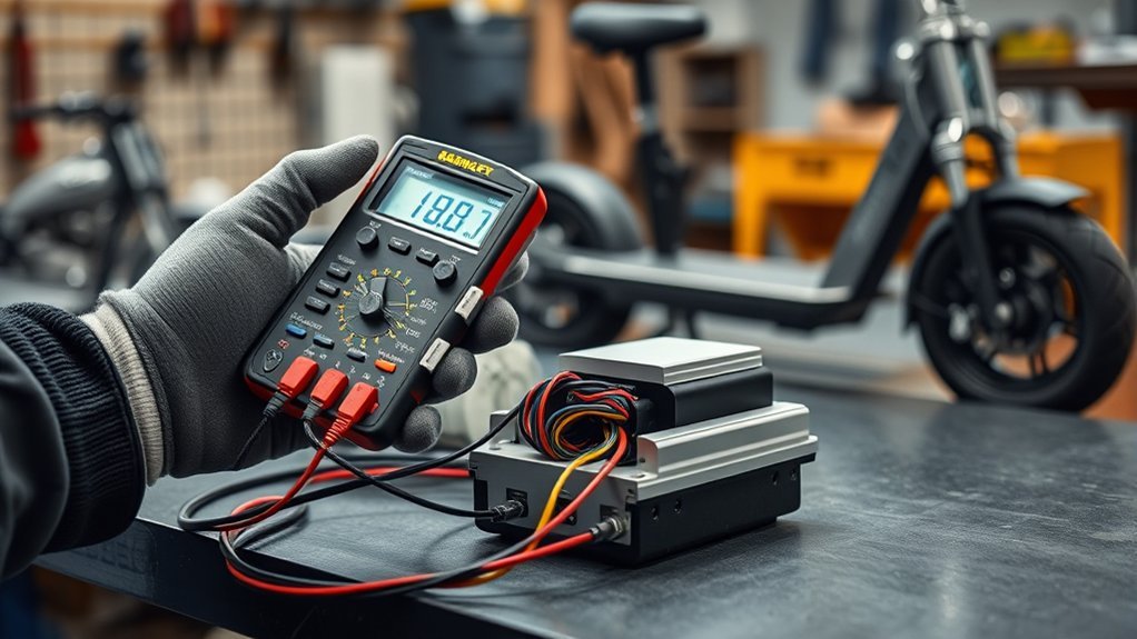
Last Updated on August 26, 2026 by Caleb Warren
Testing an electric scooter controller is mainly a process of proving what is working before blaming the controller. Start with the scooter’s error codes, battery supply, connectors, and wiring. Then check the controller or dashboard sensor supply, throttle, brake input, and motor connections. Because most modern scooters use brushless motors, do not expect a simple steady DC voltage reading from the three motor phase wires.
Quick Answer
To test an electric scooter controller, first read any fault code and confirm the correct battery voltage reaches the controller. Then inspect the wiring, check the sensor supply, throttle signal, brake input, and motor/Hall connections. Do not diagnose a brushless controller by expecting steady battery voltage on its three motor phase wires.
Key Takeaways
- Get the scooter’s wiring diagram, nominal battery voltage, maximum charging voltage, and fault-code information before testing.
- Battery voltage at the controller proves that power reached the controller; it does not prove the controller itself is healthy.
- Hall throttles commonly use a roughly 1–4 V active signal on some controllers, but the correct range is model-specific.
- Brake inputs may be switches, Hall sensors, analog sensors, or digital signals, so there is no universal continuity rule.
- Three-phase brushless motor outputs are switched/PWM signals, so an ordinary multimeter cannot always give a meaningful motor-output voltage reading.
At a Glance
| Time Required | About 15–45 minutes for basic external checks; longer if panels must be removed |
| Difficulty | Intermediate; live measurements require extra care |
| Tools Needed | Digital multimeter, model wiring diagram, basic hand tools, insulated probe tips, bright work light |
| Cost | No additional cost if you already have the required tools; replacement-part cost depends on the scooter |
Disclosure: As an Amazon Associate I earn from qualifying purchases. Some links on this page are affiliate links, at no extra cost to you.
How to Test an Electric Scooter Controller
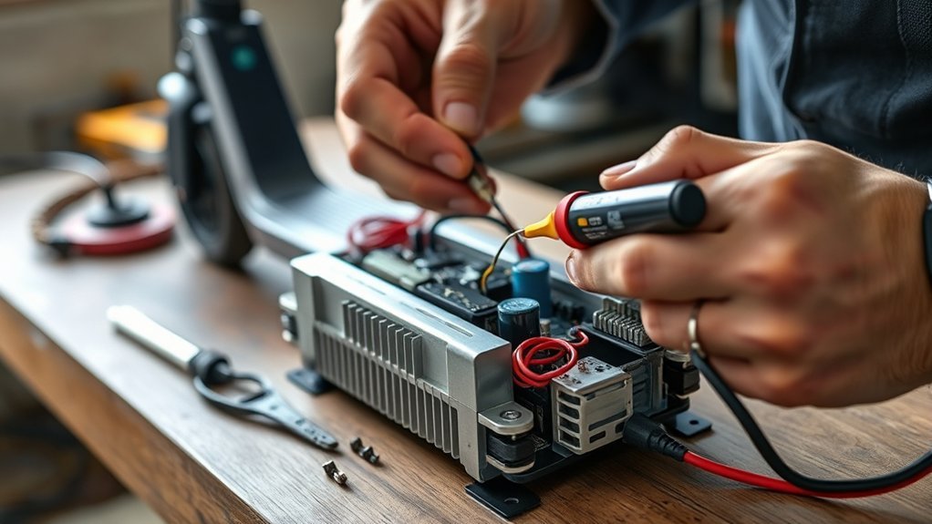
Test the controller in a logical sequence so you do not replace it because of a bad battery, brake sensor, throttle, motor connection, dashboard, or wiring harness. Modern scooters can also report useful controller faults through the dashboard or companion app, so check those diagnostics before opening the deck.
- Read fault codes first. Record any dashboard code or app message. Manufacturers such as Xiaomi and Segway document faults involving the controller, throttle, brake sensor, motor Hall sensors, battery communication, overcurrent, and wiring.
- Verify the correct battery specification. Find the nominal voltage and maximum charging voltage in the scooter manual or battery label. Do not assume every scooter is 24 V, 36 V, or 48 V.
- Power down for inspection. Turn the scooter off, unplug the charger, and disconnect the battery only when the service design allows it.
- Inspect wiring and connectors. Look for loose plugs, overheated terminals, corrosion, damaged insulation, pinched wires, or water residue.
- Confirm battery voltage reaches the controller. During an appropriate powered test, compare controller input voltage with the battery specification.
- Test control signals. Check the sensor reference supply, throttle signal, brake state, and related wiring against the model’s service information.
- Check the motor and Hall connections. Look for motor-phase, Hall-sensor, or communication faults before condemning the controller.
Battery voltage at the controller confirms the power feed. It does not, by itself, prove that the controller’s logic, sensors, MOSFETs, current sensing, or motor drive stage are working.
Safety Steps Before You Begin
Start with the scooter switched off and the charger unplugged. Disconnect the battery when the manufacturer’s service procedure calls for it. Do not rely on insulated gloves alone; use insulated tools or probe tips, keep metal jewelry away from exposed electrical connections, and work in a dry, well-lit area.
Warning: Never use resistance, continuity, or diode mode on a powered circuit. Do not open or probe inside a sealed lithium-ion battery pack unless you are trained to service high-current lithium batteries. A short circuit can cause severe heating, burns, battery damage, or fire.
Separate your tests into two groups. Perform visual inspections, continuity checks, and resistance comparisons only with the circuit powered down. Perform voltage measurements only when power is actually required for that measurement.
If you need to apply throttle during a powered test, secure the scooter so the driven wheel cannot touch the floor. A controller manufacturer’s checkout instructions similarly recommend raising drive wheels off the ground and using well-insulated tools.
Inspect cables, plugs, and terminals before applying power. Cuts, corrosion, loose pins, water, or heat damage can produce misleading meter readings and may create a short circuit when power is restored.
If the scooter is under warranty, the controller is sealed or potted, the wiring diagram is unavailable, or you cannot safely identify the test points, use the manufacturer’s service center rather than probing unknown connectors.
Before You Measure: Identify the Scooter System
Before setting the multimeter, identify four things from the scooter manual or service information:
- Nominal battery voltage and maximum charging voltage
- Controller type and connector layout
- Throttle and brake sensor type
- Motor type, including whether it uses three phase wires and separate Hall-sensor wires
For example, the Segway E2 Pro is specified with a 36 V nominal battery and a 42 V maximum charging voltage. That does not mean every 36 V scooter uses identical test limits, but it shows why nominal voltage and fully charged voltage are different numbers.
Note: Many branded scooters route throttle and brake sensor information through the dashboard before it reaches the motor controller. Do not assume every throttle or brake wire connects directly to the controller.
How to Find the Controller
The controller is commonly mounted inside the deck, frame, or another protected compartment, but its appearance varies widely. Aftermarket controllers are often rectangular aluminum boxes with multiple wire harnesses. Some branded scooters use compact or integrated control boards that do not look like a separate metal box.
Before removing a cover, switch the scooter off, unplug the charger, and follow the manufacturer’s battery-disconnection procedure if one is provided. Trace the motor harness and main power wiring only after confirming the scooter is safe to open.
Trace the motor and power harnesses to identify the controller, but confirm its location with the model’s wiring or service documentation whenever possible.
- A controller housing or board inside the deck
- Heavy battery-positive and battery-negative conductors
- Three heavier motor phase wires on many brushless systems
- Smaller Hall, throttle, brake, display, or communication wires
- Fuses, connectors, or power-distribution components nearby
Clean loose dirt around the compartment before unplugging connectors. Photograph the original connector positions if several similar plugs are present, and never force a connector or bend its pins.
How to Inspect the Controller for Damage
Begin with an external inspection. Check the controller case, harness, connectors, and surrounding compartment for heat, corrosion, water residue, loose terminals, crushed wiring, or damaged insulation. Many faults can be found without opening the electronic assembly.
Check For Burn Marks
With power disconnected, inspect accessible connectors and the controller exterior for darkened plastic, melted insulation, heat-discolored terminals, or a burnt smell. These signs can point to excessive current, poor connector contact, a short circuit, or internal component failure.
- Blackened or melted connector plastic
- Brown or blue heat discoloration on a terminal
- Charred insulation near a high-current wire
If the controller is sealed or potted, do not open it merely to look for internal damage. If the manufacturer provides a serviceable enclosure and you are qualified to open it, swollen capacitors, burned traces, or damaged components can confirm an internal failure.
Inspect Wiring And Connectors
Check every relevant harness for cuts, crushed sections, corrosion, loose terminals, backed-out pins, or overheated contacts. Verify each plug is connected to the correct mating connector.
For a power-off continuity test, disconnect the relevant circuit as required by the wiring diagram so parallel paths do not produce confusing readings. Test the suspect wire from end to end and gently move the harness while watching the meter. An intermittent reading can reveal a broken conductor or loose terminal.
Pro Tip: If a fault appears only when the handlebar turns or the stem folds, pay close attention to harness sections that repeatedly flex. A partially broken signal wire can imitate a failed controller.
Look For Swollen Components
Swollen capacitors, cracked solder joints, scorched components, or lifted circuit-board traces are genuine signs of electronic damage when they are visible on a serviceable controller. However, many scooter controllers are sealed, coated, or potted, so internal components may not be safely accessible.
- Bulging capacitor tops on an accessible board
- Scorched MOSFET or driver areas
- Cracked solder joints around high-current terminals
- Corrosion or residue from water ingress
If significant internal damage is visible, replacement is usually more practical than repeatedly powering the controller for further testing.
Check Error Codes Before Electrical Testing
A fault code can narrow the diagnosis before you touch a multimeter. Current scooter systems may detect separate problems involving the throttle, brake sensor, motor Hall sensor, controller current sampling, battery communication, temperature sensor, motor phase wiring, or controller MOSFET stage.
For example, Xiaomi’s Electric Scooter 6 Pro repair information distinguishes communication faults, controller overcurrent and current-sampling faults, motor Hall faults, brake-lever faults, battery communication faults, and controller MOSFET bridge faults. Segway’s E2 Pro documentation similarly lists throttle Hall, brake Hall, motor Hall, controller-current, motor-phase, battery-communication, and overcurrent errors.
Write down the exact code before disconnecting anything. Clearing or disconnecting components too early can erase evidence that would otherwise direct you to the failed circuit.
How to Test Electric Scooter Controller Input Voltage
Input-voltage testing determines whether the controller receives the power it is supposed to receive. It does not prove that the controller is functioning internally.
- Find the scooter’s nominal battery voltage and maximum charging voltage from its label or manual.
- Identify the controller’s main positive and negative input conductors from the wiring diagram. They may not literally be labeled BAT+ and BAT-.
- Set the multimeter to DC volts on a range higher than the battery’s maximum voltage.
- With the scooter secured and the electrical system powered as required for the test, place the meter probes only on the identified power test points.
- Compare the reading with the battery voltage measured at an approved accessible connector or with the manufacturer’s expected range.
If the battery itself has normal voltage but substantially less voltage reaches the controller, inspect the fuse, main connector, power switch or enable circuit, harness, terminals, and any battery-management protection involved in the power path.
If full battery voltage reaches the controller, continue testing. That result confirms the supply path but does not rule out a failed controller processor, internal low-voltage supply, MOSFET stage, current sensor, temperature sensor, or communication circuit.
How to Test Controller Output, Throttle, and Brake Signals
After verifying the power supply, test the low-voltage control signals. These tests are often more useful than trying to measure the controller’s three motor phase outputs with an ordinary multimeter.
Check the Sensor Reference Supply
Many controllers provide a low-voltage supply for a Hall throttle or other sensors. A common design uses a 5 V reference, but confirm the exact value and connector pins in the model documentation.
If the expected sensor supply is missing, disconnect the sensor only when the service procedure permits and test again. A shorted throttle or sensor can sometimes pull a reference supply down, while a missing reference with the sensors removed can point toward controller, dashboard, or wiring failure.
Test the Throttle Signal
A typical three-wire Hall throttle uses supply, ground, and signal conductors. The signal should change smoothly as the throttle moves, but it should not automatically be expected to travel from exactly 0 V to exactly 5 V.
For example, Kelly’s KLS-S documentation lists 1–4 V as the standard active range for a Hall throttle while also supporting other throttle configurations. Your scooter can use different thresholds.
- Confirm the sensor supply first.
- Measure the signal relative to the correct signal ground.
- Move the throttle slowly from rest to full travel.
- Look for a smooth change without sudden dropouts or jumps.
- Compare the idle and full-throttle values with the scooter’s specification.
A signal that is stuck, missing, or erratic can indicate a throttle, wiring, dashboard, or controller-input problem.
Test the Brake Cutoff Signal
Do not assume the brake switch must have continuity when the lever is released. Electric scooters may use a normally open switch, normally closed switch, Hall-effect brake sensor, analog brake input, or dashboard-based brake signal.
Instead, identify the brake input type and verify that its electrical state changes correctly when the lever is pressed and released. A brake signal that stays active can prevent the motor from responding to the throttle.
Xiaomi’s fault documentation, for example, specifically identifies a brake lever that does not return to its normal position at startup as a condition that can trigger a brake fault.
Note: Do not perform continuity testing while the circuit is powered. Use voltage testing for live sensor signals and continuity or resistance mode only on an isolated, powered-off circuit.
How to Test Motor Phase and Hall Sensor Wiring
Most modern electric scooters use a three-phase brushless DC or permanent-magnet motor. These systems commonly have three heavier phase conductors plus smaller Hall-sensor wires, although sensorless designs also exist.
First inspect the three phase connectors for melting, looseness, corrosion, or discoloration. Then inspect the Hall connector for bent pins, broken wires, or moisture. A motor Hall fault can prevent starting or cause rough operation even when the controller receives full battery voltage.
With the system powered down and disconnected according to the service procedure, an experienced technician can compare the three motor phases for obvious open circuits or gross shorts. Very low winding resistance is normal on many hub motors, so an ordinary handheld meter may not accurately measure the actual winding resistance. The useful check is usually whether all three phases behave similarly rather than whether they match a universal resistance value.
Hall sensors can also be checked for switching if the service documentation identifies the supply, ground, and Hall signal wires. Slowly rotating the wheel should cause the Hall outputs to change states. Exact voltage thresholds and pin assignments vary.
Why a Multimeter Is Limited on Motor Output
A brushless controller does not simply send one adjustable DC voltage to the motor. It rapidly switches the three phases in a controlled sequence. Texas Instruments’ BLDC motor-control documentation describes PWM control and Hall-based commutation used to drive brushless motors.
Because of that switching, a standard multimeter may display an average, changing, or unstable number on a motor phase. “Zero volts” or “nearly battery voltage” is therefore not a universal pass/fail test for a brushless scooter controller.
An oscilloscope, current probe, manufacturer diagnostic software, or dedicated controller test procedure can reveal much more about the motor-drive waveform, but those are advanced tests.
Why an Electric Scooter Controller Clicks But Won’t Run?
If you hear a click but the motor does not run, do not immediately assume the controller’s relay has failed. Depending on the scooter, the sound may come from a contactor, mechanical part, brake system, or another component. Some scooter controllers do not use a user-serviceable mechanical relay at all.
Start with battery voltage under load, brake and throttle signals, fault codes, startup interlocks, and motor connections.
Battery Voltage Under Load
A weak battery, high-resistance connector, damaged wiring connection, or BMS protection event can allow the scooter to show normal voltage at rest but fail when the controller requests significant current.
Measure the accessible battery or controller input voltage at rest and, when it can be done safely, while the scooter attempts to drive the elevated wheel. If voltage collapses when throttle is applied and quickly recovers when the load disappears, investigate the battery, BMS, fuse, and high-current connectors before replacing the controller.
Do not use a fixed rule such as “below 23 V means the battery is bad” or “a healthy pack drops less than 1 V.” Acceptable loaded voltage depends on the battery’s nominal voltage, state of charge, current demand, temperature, age, wiring resistance, and the manufacturer’s undervoltage settings.
- Compare loaded voltage with the scooter’s actual specification.
- Inspect connectors for heat or voltage drop.
- Repeat the test with the battery adequately charged.
- Stop if a connector becomes hot, discolored, or begins to smell.
Do not open the battery pack to check individual cell groups as a routine DIY controller test. Segway’s battery safety guidance, for example, warns users not to disassemble the battery and states that it has no user-serviceable parts.
Brake And Throttle Checks
When battery voltage is stable but the scooter refuses to drive, verify the throttle and brake states. A valid throttle signal with a brake input stuck in the active state may cause the controller to intentionally block motor power.
Check for:
- A throttle signal that changes smoothly through the manufacturer’s expected range
- A brake input that changes correctly when the lever is pressed and released
- Loose, wet, or corroded signal connectors
- A dashboard error for the throttle or brake sensor
- An app lock, immobilizer, or startup condition that prevents acceleration
Some scooters also require the scooter to be rolling before the throttle becomes active. If your model uses a kick-start or non-zero-start setting, meet the specified startup condition before interpreting a lack of motor response as a controller fault.
Relay Or Controller Fault
If the scooter actually uses a relay or contactor, identify it from the wiring diagram before testing it. A click only proves that something mechanically moved; it does not prove that the contacts carried current.
If battery voltage reaches the controller, throttle and brake inputs are correct, motor/Hall wiring is intact, the scooter is not locked, and manufacturer diagnostics report an internal controller fault, the controller becomes a much stronger suspect.
Manufacturers may identify internal faults directly. Xiaomi, for example, documents controller MOSFET bridge, current-sampling, overcurrent, water-ingress, and communication failures for which controller replacement may be required.
- A contactor may click even when its contacts are damaged.
- An internal controller fault may exist with normal battery input voltage.
- A startup interlock or kick-start setting can imitate a dead controller.
- A motor Hall or phase fault can prevent drive without a battery problem.
How to Spot Water, Heat, and Wiring Damage
Water, overheating, and wiring faults can cause intermittent shutdowns, error codes, rough motor operation, or complete loss of drive.
Inspect the controller compartment for:
- Green or white corrosion around terminals
- Mineral residue or moisture trails
- Melted connector housings
- Brown or black heat discoloration
- Swollen or cracked accessible electronic components
- Pinched or rubbed-through wire insulation
- Loose plugs or terminals that have backed out of a connector
Xiaomi specifically lists water exposure as a possible cause in some controller-fault scenarios. If water has entered an electronic controller, do not repeatedly power it on to “see if it works.” Disconnect power according to the service procedure and allow a qualified technician to assess the damage.
After normal riding, some controller warmth is expected because the power electronics generate heat. What matters is abnormal overheating, temperature-related shutdowns, a temperature error code, melted parts, or operation outside the manufacturer’s temperature limits.
Advanced MOSFET Short Check
If all basic checks point toward the controller, an experienced technician may perform a powered-off diode or resistance comparison between the motor phase terminals and the controller’s DC bus. This can sometimes expose a MOSFET that has failed short.
The battery must be disconnected, the controller must be handled according to its service procedure, and the same meter mode and probe orientation must be used for each phase. Compare the three phases with one another rather than applying a universal resistance or diode-voltage threshold.
Warning: Do not perform this test on a powered controller, and do not short a phase terminal to battery positive or negative with a meter probe. If the controller is sealed or its internal design is unknown, stop at the external diagnostic tests.
Common Test Results and What They Mean
| Test Result | Likely Area to Check |
| No battery voltage reaches controller | Battery/BMS protection, fuse, switch, connector, or power harness |
| Correct battery input but missing sensor reference | Shorted sensor, dashboard/wiring fault, or controller low-voltage supply |
| Sensor supply good but throttle signal does not change | Throttle, throttle wiring, dashboard, or signal-input circuit |
| Brake input stays active | Brake sensor/switch, lever, wiring, or dashboard |
| Battery voltage collapses only under throttle | Battery, BMS, fuse, connector, or high-current wiring |
| Motor Hall error or phase error | Motor Hall sensors, phase wiring, connectors, motor, or controller sensing circuit |
| All external inputs test correctly but controller reports an internal MOS/current-sense fault | Controller is a strong replacement candidate |
When to Repair or Replace the Controller
If normal battery voltage reaches the controller but the scooter still does not run, continue ruling out the throttle, brake sensor, dashboard communication, startup interlocks, motor Hall sensors, phase wiring, and connectors before replacing the controller.
Normal battery voltage with no motor operation does not automatically prove a failed controller; it becomes convincing only after the control inputs, wiring, motor feedback, and manufacturer diagnostics have been checked.
Replacement is usually justified when manufacturer diagnostics identify an internal controller fault or when there is clear physical evidence such as severe water ingress, melted power electronics, burned circuit-board areas, shorted power devices, or repeated temperature shutdowns caused by an internal failure.
- Burned or melted controller terminals
- Heavy corrosion inside an electronic assembly
- Confirmed MOSFET bridge fault
- Controller current-sampling or internal sensor failure
- Persistent internal controller error after wiring and sensors are verified
- Intermittent shutdown caused by confirmed controller overheating
External connector damage can sometimes be repaired without replacing the entire controller. Internal board-level repairs require the right diagnostic equipment and electrical experience. On branded scooters, replacement can also require compatible firmware, pairing, serial-number programming, or authentication, so check the manufacturer’s service requirements before installing a new controller.
Sources
- Xiaomi Electric Scooter 6 Pro Error Code and Repair Guideline — controller, brake, Hall sensor, communication, water-ingress, MOSFET, and battery fault guidance.
- Segway Ninebot E2 Pro Product Manual — battery specifications, fault codes, controller, throttle, brake, Hall-sensor, and maintenance information.
- Segway KickScooter ES-Series User Manual — lithium-ion battery safety and electrical specifications.
- Kelly KLS-S Cheetah Series Motor Controller User Manual — throttle ranges, controller wiring, Hall sensors, brake inputs, and BLDC controller specifications.
- Texas Instruments 1-PWM Brushless DC Motor Control Reference Design — three-phase BLDC commutation, Hall sensing, and PWM motor control.
Frequently Asked Questions
How to Tell if a Scooter Controller Is Bad?
A controller becomes the likely fault when the correct battery voltage reaches it, wiring and connectors are sound, throttle and brake inputs are valid, motor Hall and phase connections test correctly, startup interlocks are satisfied, and the scooter still reports an internal controller fault or produces no valid motor operation. Burned electronics, severe water damage, or confirmed MOSFET faults are stronger evidence.
How to Test a Scooter Controller With a Multimeter?
Use DC-voltage mode to verify the controller’s battery input, sensor reference, throttle signal, and any model-specific live signals. With power disconnected, use continuity, resistance, or diode mode for approved wiring and component checks. Do not judge a three-phase brushless controller solely by looking for steady battery voltage on its motor phase wires.
How Can I Test if My Controller Is Working?
Confirm that the controller receives the correct battery voltage, that its required sensor supply is present, and that the throttle, brake, motor Hall sensors, and communication wiring behave as the manufacturer specifies. If those checks pass and the scooter operates without controller-related error codes, the controller is probably functioning normally.
How to Reset an Electric Scooter Controller?
There is no universal electric scooter controller reset button or reset sequence. Use the procedure in the scooter’s manual or companion app. Some faults clear after a normal power cycle, while others require service. Disconnect the battery only when the manufacturer’s service procedure permits it; do not assume battery disconnection is a standard reset method.
What Voltage Should an Electric Scooter Throttle Show?
The correct voltage depends on the throttle and controller. A three-wire Hall throttle often receives about a 5 V supply, while its signal may operate over a narrower range such as roughly 1–4 V on some controllers. Always compare the measurement with the scooter or controller documentation rather than assuming an exact 0–5 V sweep.
Can I Test the Motor Output Voltage With a Multimeter?
A normal multimeter can show that activity is present, but it is not a reliable universal test of a brushless controller’s three motor phases. The controller rapidly switches and commutates those phases with PWM, so the meter may display an averaged or unstable value. Manufacturer diagnostics or an oscilloscope provide more meaningful motor-drive information.
Should I Open the Scooter Battery to Test Individual Cells?
Not as part of normal DIY controller troubleshooting. Lithium-ion packs can deliver very high short-circuit current and may contain no user-serviceable parts. Keep routine testing at approved external connectors and leave internal cell-group diagnosis to a qualified battery technician.
Conclusion
A reliable electric scooter controller diagnosis is based on elimination, not one voltage reading. Start with fault codes and the scooter’s exact electrical specifications. Confirm that the battery supply reaches the controller, inspect the power and signal wiring, then check the sensor reference, throttle, brake input, motor Hall sensors, and phase connections.
Remember that most modern scooter motors are three-phase brushless designs. Their controllers use rapidly switched motor phases, so an ordinary multimeter cannot prove controller health by simply looking for battery voltage at the motor outputs. If every external input and connection checks correctly and the scooter reports an internal controller, MOSFET, current-sensing, or temperature fault, replacement becomes the more reasonable diagnosis.
