
Last Updated on July 23, 2026 by Caleb Warren
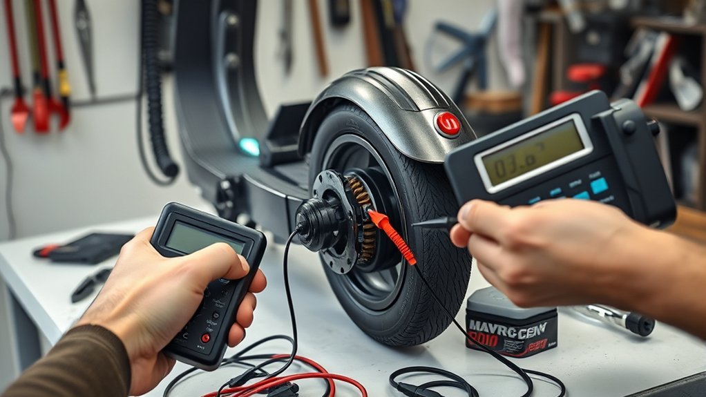
Testing an electric scooter motor with a multimeter can help you separate a motor fault from a battery, wiring, Hall-sensor, or controller problem. Most scooter drive motors are three-phase brushless DC (BLDC) motors, so you should begin with power-off checks and only run the wheel after the static tests pass.
Quick Answer
Disconnect the battery and controller before resistance tests. Compare all three phase-wire pairs, then check each phase against the motor case. Power the Hall circuit with its specified low-voltage supply and rotate the wheel slowly. Each signal should switch between low and high. Finish with a controller-powered, wheel-off-ground test.
Key Takeaways
- Turn the scooter off and isolate the motor before using resistance or continuity mode.
- Phase-to-phase readings should be low and closely matched, but the exact value depends on the motor and your meter.
- A phase wire should not show continuity to the motor case with a standard multimeter.
- Hall-sensor wire colors and pin order vary, so identify supply, ground, and signal wires from the wiring diagram.
- Do not apply raw DC to a BLDC motor and expect it to spin. Use the correct controller for a no-load test.
At a Glance
| Time Required | About 20–40 minutes |
| Difficulty | Moderate |
| Tools Needed | Digital multimeter, basic hand tools, scooter stand or blocks, wiring diagram, and an optional current-limited Hall-sensor supply |
| Cost | No added cost if you already own a suitable multimeter; tool prices vary |
Warning: Stop if the battery is swollen, leaking, unusually hot, wet, punctured, or giving off an odor. Do not open a sealed lithium-ion battery pack. Keep the drive wheel off the ground during powered testing, and never use resistance mode on an energized circuit.
Disclosure: As an Amazon Associate I earn from qualifying purchases. Some links on this page are affiliate links, at no extra cost to you.
Before You Start: Safety and Motor Type
Disconnect the charger, turn the scooter off, and remove or unplug the battery if the model allows it. Follow the manufacturer’s shutdown and service instructions. The U.S. Consumer Product Safety Commission warns that damaged or noncompliant micromobility battery systems can create a serious fire risk, so battery damage is not a do-it-yourself motor-test issue.
A BLDC motor needs electronic commutation from a controller. As Microchip’s BLDC motor guide explains, the controller switches current through the three phases in sequence. This is why a direct DC connection is not a proper spin test.
Many scooter motors have three thicker phase wires plus a smaller Hall-sensor connector. Some also include temperature or speed-signal wires. Do not identify wires by color alone because manufacturers use different pinouts.
Tools for Motor Testing

Use a digital multimeter that can measure DC voltage, resistance, continuity, and low AC voltage. You will also need the correct screwdrivers or Allen keys, a stable stand or blocks to lift the drive wheel, and the scooter’s wiring diagram or service manual.
A current-limited bench supply can help with a disconnected Hall-sensor test, but only after you confirm the correct supply voltage and pinout. An insulation resistance tester is optional professional equipment. Do not connect one while Hall sensors, a temperature board, the controller, or other electronics remain attached, and use only a test voltage approved by the motor manufacturer.
Pro Tip: Touch the meter probes together before measuring the phase wires. Record the lead resistance or use the meter’s REL/zero function. Scooter motor resistance can be so low that probe and contact resistance noticeably affect the reading.
Check Wiring, Damage, and Heat Signs
Inspect the full motor cable from the axle to the controller. Pay special attention where the cable exits the axle, bends around the frame, or passes through clips. Cuts, crushed insulation, bent pins, loose terminals, water marks, or melted plastic can cause a motor symptom even when the windings are healthy.
Inspect Loose Connectors
Unplug each motor connector only after the scooter is powered down. Look for pushed-back pins, corrosion, dirt, moisture, or a connector that does not lock firmly. Gently tug each wire near the terminal; the conductor should not move inside the housing. Repair damaged terminals with the correct connector rather than twisting wires together.
Use continuity mode only on an isolated wire. Fluke’s continuity guidance recommends testing with the circuit de-energized and the component isolated so parallel paths do not mislead the reading.
Look for Heat Damage
Check for darkened terminals, melted connector shells, brittle insulation, a burnt smell, or discoloration near the axle. These signs can point to a loose high-resistance connection, excessive current, overload, blocked cooling, or internal damage. If the motor became extremely hot during normal use, do not repeat a long test ride until you find the cause.
An infrared thermometer or thermal camera can help compare temperatures after a brief controlled test, but it does not replace electrical testing. Follow the scooter manufacturer’s temperature limits rather than using a universal pass-or-fail number.
Check Wire Insulation
With the motor disconnected, inspect every phase and Hall wire for cuts, abrasion, flattening, and exposed copper. A standard multimeter can reveal a direct short, but an “OL” reading does not prove that insulation will remain safe under every operating condition.
For a basic check, measure from each phase wire to the metal motor case. The meter should show OL or no continuity. If any phase shows a stable low-resistance path to the case, do not power the motor. A professional insulation-resistance test may be useful after the motor and all low-voltage electronics are fully isolated, but the acceptable test voltage and resistance limit must come from the motor manufacturer.
Check Battery Voltage and Connections
Set the multimeter to DC voltage on a range above the pack’s maximum possible voltage. Place the black probe on battery negative and the red probe on battery positive only if the terminals are safely accessible and you know how to avoid a short. Compare the result with the scooter manual, battery label, and charger-output specification.
Do not expect a battery to read exactly its nominal label voltage, and do not treat “below 80% of nominal” as a universal failure point. Battery voltage changes with chemistry, state of charge, temperature, rest time, and load. Texas Instruments’ battery-gauging overview explains that a relaxed open-circuit voltage must be interpreted with the correct battery profile, while voltage under load can be misleading.
If the battery has normal voltage at its output but the same voltage is missing at the controller input, inspect the fuse, switch, wiring harness, connectors, and battery-management-system path. If voltage falls sharply only when throttle is applied, the battery, connector, BMS, or wiring may be unable to supply current. A voltage check alone cannot measure battery capacity or prove the motor is bad.
Test Electric Scooter Motor Windings
Disconnect the motor phase leads from the controller. Confirm power is off, then compare resistance between all three phase-wire pairs. Label the wires A, B, and C if their colors are unclear. The important result is balance between the three readings, not a generic “correct” number.
Phase Resistance Check
- Set the multimeter to its lowest resistance range.
- Short the probes together and note the lead resistance, or use the REL/zero function.
- Measure A to B, B to C, and C to A.
- Hold the probes firmly in the same place for each test.
- Repeat any reading that changes when you move the probes.
Fluke’s resistance-testing instructions state that the circuit must be turned off and any stored energy discharged before an ohms test. Record the raw readings and the lead-compensated readings if your meter does not zero automatically.
Compare Windings Evenly
| Test | Healthy Pattern | Possible Problem |
| A–B, B–C, C–A | All three are low and closely matched | One open or repeatably different reading suggests a winding, cable, connector, or test-contact fault |
| Each phase to motor case | OL or no continuity on a standard multimeter | A stable low-resistance reading suggests damaged insulation or a pinched wire |
Do not assume “a few ohms” is normal for every scooter. Some BLDC windings are below one ohm, and a basic multimeter may show mostly probe and contact resistance. Compare the readings under the same conditions and check the manufacturer’s specification when available.
Spot Open or Shorted Windings
An OL reading between one phase pair can indicate an open winding, broken phase wire, or failed connector. A single pair that reads repeatably different from the other two can indicate a poor connection or winding fault. However, a simple ohms test may miss a turn-to-turn short because the resistance change can be smaller than the meter can resolve.
- Compare all three phase pairs with the same probe pressure.
- Recheck suspicious results directly at the motor-side connector.
- Test every phase against the case.
- Inspect the axle cable before assuming the winding itself has failed.
- Record the values so you can compare them later.
For a quick drag comparison, leave all phase leads separate and rotate the wheel by hand. Then short two phase leads together while the scooter remains unpowered and rotate the wheel again. You should feel more electrical braking with the pair shorted. This confirms that a current path exists, but it does not prove that every turn or Hall sensor is healthy.
Compare Generated Voltage Between Phases
You can use the motor as a small generator for an additional check. Keep it disconnected from the controller, set the meter to low AC voltage, and rotate the wheel at a steady speed while measuring A–B, B–C, and C–A. The three readings should be similar when the wheel speed is similar.
A missing or repeatably low reading on one pair can point to an open phase, damaged connection, or winding problem. Because hand speed changes easily and many meters respond slowly, use this as a comparison test rather than an exact voltage specification.
Verify Hall Sensors With a Multimeter
First identify the Hall supply, ground, and signal wires from the wiring diagram. A common layout has one low-voltage supply wire, one ground wire, and three Hall-signal wires, but wire colors and pin order are not universal.
- Lift the drive wheel and keep the throttle untouched.
- Reconnect the Hall connector to the controller if safe back-probing points are available.
- Turn the scooter on and measure the Hall supply between its supply and ground wires. It should match the controller’s specification, commonly near 5V.
- Measure one Hall signal to Hall ground while rotating the wheel slowly by hand.
- Repeat for the other signal wires.
A working digital Hall signal should switch between a low level near 0V and a high level near its pull-up supply. It may not reach exactly 0.00V or 5.00V. Rotate slowly because a digital multimeter may average rapid switching.
If you test a disconnected sensor board with a bench supply, use the specified voltage, limit the current, and verify the pinout first. Many digital Hall sensors use an open-drain output. The Texas Instruments DRV5015 documentation shows a 2.5V-to-5.5V Hall latch with an open-drain output, which requires a pull-up path for a valid high reading.
Note: A signal that stays fixed does not automatically prove the Hall sensor is bad. Confirm the supply, ground, connector, pull-up, and signal-wire continuity before opening the motor.
Run a No-Load Motor Test
After the wiring, phase, case, generated-voltage, and Hall checks pass, reconnect the motor to its original compatible controller. Secure the scooter so the drive wheel cannot touch the floor, clothing, cables, or your hands. Start at the lowest possible throttle and run the wheel only long enough to observe its behavior.
Warning: Do not apply about 5V DC directly across phase wires as a spin test. A three-phase BLDC motor needs timed electronic commutation, and a fixed DC connection can create heavy current, heating, or misleading results.
- Watch for smooth startup and steady rotation.
- Listen for scraping, grinding, clicking, or repeated pulsing.
- Check whether the wheel starts only after you push it by hand.
- Stop if a connector, phase wire, controller, or motor heats quickly.
- Check for side-to-side play that may indicate a bearing or axle problem.
A good no-load run does not prove the system will work under full rider load. If static motor tests pass but the wheel still jerks, cuts out, or will not start, investigate the controller, throttle, brake-cutoff switches, current limits, and connector pinout. The Grin Technologies troubleshooting library includes separate motor Hall-sensor and controller checks that help isolate these faults.
Identify Common Motor Faults
| Symptom | Likely Areas | What to Check |
| Motor does not move | Battery path, controller, brake cutoff, throttle, open phase, or Hall supply | Battery voltage at controller, phase continuity, Hall supply, and controller inputs |
| Jerks or starts only with a push | Hall signal, phase connection, controller commutation, or wrong phase/Hall pairing | All three Hall transitions, connector pinout, and controller compatibility |
| Grinding or rough rotation | Bearings, bent axle, rotor contact, loose hardware, or debris | Wheel play, free rotation with phases open, and mechanical inspection |
| Cuts out under load | Weak battery, BMS cutoff, overheated connector, controller limit, or damaged phase cable | Voltage sag, hot spots, connector condition, and error codes |
| One phase pair is open or different | Broken wire, terminal, axle cable, or winding | Repeat resistance and generated-voltage tests at the motor connector |
Use more than one test before condemning the motor. A loose connector can imitate a winding fault, a failed controller can imitate a Hall fault, and a worn bearing can cause noise even when all electrical readings look normal.
Repair Faults and Prevent Future Damage
Replace burnt connectors with properly rated parts, repair damaged cables with secure insulated connections, and replace failed Hall sensors only with electrically and physically compatible parts. If the windings are shorted, grounded, badly overheated, or water-damaged, replacing the motor assembly is often safer and more practical than a home rewind.
- Route the axle cable without sharp bends or crushing.
- Keep connectors dry and fully locked.
- Correct loose terminals before they create heat.
- Check wheel bearings and axle hardware during routine service.
- Record phase and Hall readings after a successful repair.
Retest the repaired circuit before riding. Confirm balanced phase readings, no phase-to-case continuity, correct Hall switching, smooth no-load operation, and no rapid heating. Stop and use a qualified repair technician if you cannot identify the battery terminals safely, the motor contains damaged internal wiring, or the scooter still cuts out after the motor passes its tests.
Frequently Asked Questions
How can you tell if an electric scooter motor is bad?
Common signs include an open phase, one phase-pair reading that differs from the others, continuity from a phase wire to the case, a Hall signal that does not switch after its supply and wiring are verified, unequal generated voltage, grinding, or rapid overheating. Confirm the controller and battery before replacing the motor.
How do you tell if an electric motor is bad with a multimeter?
With the motor isolated, compare resistance across all phase pairs and check every phase against the case. An open pair, a repeatable imbalance, or a low-resistance path to the case is a fault sign. A basic multimeter cannot detect every turn-to-turn short, so combine resistance, Hall, generated-voltage, and mechanical checks.
What are three common electrical problems in a scooter motor system?
Three common problems are loose or overheated connections, broken or shorted phase wiring, and failed Hall-sensor circuits. Battery voltage sag, controller faults, and brake-cutoff inputs can create similar symptoms, so test the whole drive system rather than assuming the motor has failed.
How do you test a three-wire brushless motor?
Disconnect the three phase wires from the controller. Measure A–B, B–C, and C–A on the lowest ohms range, then check each wire against the motor case. The three pair readings should be closely matched, and the case checks should show OL. You can also compare AC voltage generated across each pair while rotating the wheel.
Should a motor phase wire have continuity to ground?
No. With the motor disconnected, a standard multimeter should normally show OL or no continuity between each phase wire and the metal motor case. A stable low-resistance reading can indicate damaged insulation, a pinched cable, moisture, or an internal winding-to-case fault.
Can you spin-test a BLDC scooter motor without a controller?
Not by applying fixed DC across the phase wires. A BLDC motor needs a controller or another proper three-phase commutation source. Without the controller, you can still perform resistance, phase-to-case, shorted-phase drag, Hall-sensor, and generated-voltage comparison tests.
Conclusion
To test an electric scooter motor with a multimeter, work from simple checks to powered checks. Inspect the cable and connectors, verify the battery path, compare all three phase pairs, check each phase against the case, test Hall switching, and compare generated voltage. Only then reconnect the correct controller for a brief wheel-off-ground run.
No single reading proves the motor is perfect. Balanced results across several tests give you a stronger diagnosis, while one clear failed result tells you where to continue. Stop if you find battery damage, a phase-to-case short, rapid heating, or wiring you cannot identify safely.
Sources
- Fluke: How to Measure Resistance With a Digital Multimeter — power-off resistance-testing procedure and meter setup.
- Microchip: BLDC Motor Commutation and Control Architectures — why a BLDC motor requires electronic commutation.
- Texas Instruments: DRV5015 Hall-Effect Latch — Hall-sensor supply range and open-drain output behavior.
- Texas Instruments: Fundamentals of Battery Gauging — open-circuit voltage, chemistry profiles, and state-of-charge interpretation.
- Grin Technologies: Motor and Controller Troubleshooting — practical separation of Hall-sensor, motor, and controller faults.
- U.S. Consumer Product Safety Commission: Micromobility Battery Safety — battery fire risk and applicable safety standards.
