
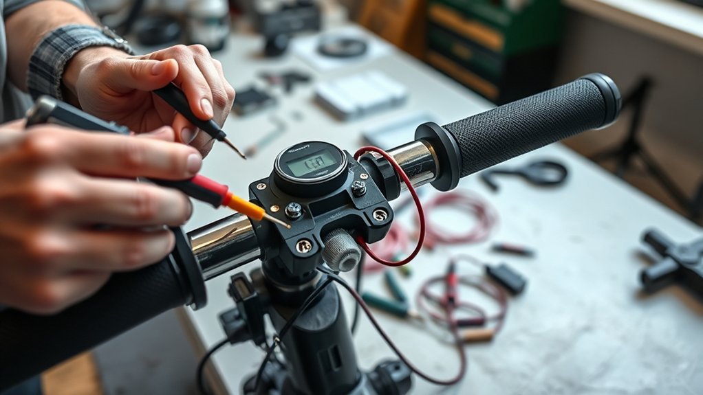
Last Updated on July 23, 2026 by Caleb Warren
Testing an electric scooter throttle is mainly a process of checking three circuits: the low-voltage power supply, ground, and the variable signal sent to the controller. The test is straightforward when you identify the correct wires, secure the scooter, and compare your readings with the specifications for your exact model.
Quick Answer
To test a common three-wire Hall-effect scooter throttle, first measure the controller’s supply between the throttle power and ground wires. It should normally be close to 5V. Then measure signal to ground while moving the throttle slowly. A healthy signal should rise smoothly, commonly from about 0.8–1.0V at rest to around 4.0–4.3V at full travel.
Key Takeaways
- Confirm the throttle type and connector pinout before trusting wire colors.
- Measure the controller’s supply between power and ground before testing the signal wire.
- A common Hall-throttle signal rises from roughly 0.8–1.0V to about 4.0–4.3V, but model specifications take priority.
- A smooth signal with no motor response can point to a brake cutoff, controller lockout, battery problem, or controller fault.
- Use continuity mode only after power is removed and the circuit is isolated.
At a Glance
| Time Required | 20–40 minutes |
| Difficulty | Moderate |
| Tools Needed | Digital multimeter, thin back-probe pins, basic hand tools, stable scooter stand, and the model’s wiring diagram |
| Cost | No additional cost if you already own the tools; replacement-throttle cost varies by scooter and connector type |
Warning: Secure the scooter before an energized test and lift the driven wheel off the floor. Keep hands, hair, clothing, tools, and test leads away from the wheel. Disconnect the charger. Never use resistance or continuity mode on a powered circuit, and never connect the scooter’s full battery voltage directly to a 5V throttle.
Disclosure: As an Amazon Associate I earn from qualifying purchases. Some links on this page are affiliate links, at no extra cost to you.
What You Need to Test a Throttle
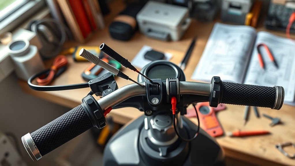
Gather the following tools before opening the scooter or disconnecting the throttle:
- A digital multimeter that can measure low DC voltage
- Thin back-probe pins or needle probes
- Basic screwdrivers or hex keys for accessing the connector
- A secure stand that keeps the driven wheel off the floor
- The scooter’s wiring diagram, service manual, or controller pinout
- A regulated 4.5V–5V DC source only if you plan to perform a compatible off-scooter test
For voltage testing, place the black meter lead in the COM jack and the red lead in the V/Ω jack. Select DC voltage, shown on most meters as a solid line over a dashed line. Do not put the red lead in the current or amp jack when measuring voltage. The Fluke DC-voltage guide explains the correct meter setup.
Note: This procedure mainly applies to a common three-wire Hall-effect throttle. Simple on/off throttles, resistance-based throttles, dual-channel throttles, and throttles with displays or key switches may use different circuits. Follow the manufacturer’s test procedure when your throttle does not match the three-wire design.
Inspect Throttle Wires and Power
Turn the scooter off before touching connectors. If the battery has an accessible service connector, disconnect it before unplugging or repairing the throttle harness.
- Trace the throttle cable from the handlebar to the controller or main harness.
- Look for crushed insulation, cuts, melted sections, sharp bends, and stretched wires.
- Check the connector for water, green corrosion, bent pins, loose terminals, or a cracked housing.
- Confirm that the connector is fully seated and that no terminal has pushed backward into the housing.
- Check that the throttle returns freely to its released position without sticking.
Most basic Hall throttles use three electrical functions:
- Power supply: commonly close to +5V
- Ground: the low-voltage reference for the supply and signal
- Signal: a variable voltage that changes with throttle position
Red, black, and green or white are common wire colors, but they are not guaranteed. Some throttles use blue as ground or signal. A throttle with a display, battery gauge, ignition switch, lights, or speed selector can also contain wires carrying battery voltage. Do not probe an unidentified wire based only on its color.
Pro Tip: Photograph the connector and mark its orientation before unplugging it. When back-probing, slide a thin probe beside the wire seal from the rear of the connector. Do not force a large probe into the front because it can spread the terminal and create an intermittent connection.
Measure Throttle Voltage With a Multimeter
Test the power supply first. A throttle cannot produce a valid signal if it does not receive the correct low-voltage supply and ground.
- Secure the scooter with its driven wheel off the floor.
- Reconnect the throttle if you unplugged it.
- Set the meter to DC volts.
- Turn on the scooter without touching the throttle.
- Place the black probe on the confirmed throttle ground.
- Place the red probe on the confirmed throttle power wire.
- Record the supply voltage.
- Move the red probe to the signal wire while keeping the black probe on ground.
- Record the signal at rest, midway, and at full throttle.
- Release the throttle and confirm that the signal returns smoothly to its starting value.
Many common Hall throttles receive about 5V and produce roughly 0.8–1.0V at rest and 4.0–4.3V at full travel. For example, Kelly Controls lists a 5V input and a 0.8–4.2V output for several throttle models, while the ElectricScooterParts throttle-testing guide uses approximately 0.8–4.3V. Your scooter’s manual or throttle specification takes priority.
| Measurement | Typical Result | What It Suggests |
|---|---|---|
| Power to ground | Close to 5V on many systems | The controller’s throttle supply is present |
| Signal to ground at rest | Often about 0.8–1.0V | Normal released signal if it matches the model specification |
| Signal to ground at full travel | Often about 4.0–4.3V | Normal full-throttle signal if it matches the model specification |
| Signal rises smoothly | No jumps or dropouts | Throttle sensor and cable are probably working |
| Signal remains at 0V | No usable output | Missing supply, bad ground, open signal wire, wrong pin, or failed throttle |
| Signal remains near supply voltage | Little or no change | Wrong wire, signal shorted to power, incompatible throttle, or internal fault |
| Signal jumps or drops out | Unstable reading | Loose probe, damaged cable, poor connector, worn mechanism, or failed sensor |
Test Throttle Response on the Scooter
An on-scooter test is usually the most useful test because it checks the throttle with the scooter’s controller, wiring, connectors, and ground reference connected normally.
Throttle Supply-Voltage Check
Measure between the throttle’s power and ground wires. Do not measure the 5V supply by probing the signal wire.
If the expected supply is missing or very low:
- Confirm the scooter is fully turned on and not only in standby mode.
- Check the battery charge, main fuse, ignition or key-switch circuit, and controller connectors.
- Inspect the 5V supply wire and ground wire for an open circuit or short.
- Check whether another sensor on the controller’s 5V rail is pulling the supply down.
- Review controller fault codes or display errors.
Do not condemn the throttle until the correct supply and ground are present.
Signal Output Test
Keep the black probe on the confirmed ground and move the red probe to the confirmed signal wire. Slowly move the throttle through its full travel.
- Record the released-throttle voltage.
- Move the throttle slowly and watch for a steady increase.
- Pause at several positions to check stability.
- Record the full-travel voltage.
- Release the throttle and confirm that the reading returns immediately and smoothly.
A normal throttle should not remain at a high signal when released. Stop testing if the motor begins turning unexpectedly, the throttle sticks, a connector becomes hot, or the reading indicates that you may be probing a battery-voltage wire.
What the Voltage Readings Mean
The most important result is not one exact number. It is whether the supply is correct and whether the signal changes smoothly across the range expected by the controller.
A throttle can produce a smooth voltage and still fail to move the scooter if the controller is blocking drive because of a brake input, startup protection, fault code, ignition problem, or incompatible throttle setting.
- Correct supply and smooth signal: The throttle and its main wiring are probably working. Continue with controller, brake-cutoff, battery, motor, and fault-code checks.
- Correct supply but no signal: Check the signal terminal, connector, cable, throttle ground, and throttle assembly.
- No supply: Diagnose the controller’s low-voltage supply, ignition circuit, wiring, fuse, battery, and connected sensors.
- Signal changes only when the cable is moved: Suspect a broken conductor or loose terminal.
- Signal starts too high: Check for a stuck throttle, incorrect wiring, wrong throttle type, bad sensor, or controller high-throttle lockout.
- Signal range differs slightly from 0.8–4.3V: Compare it with the exact model specification before replacing the throttle.
A linear Hall sensor by itself may have a quiescent output near half its supply voltage. However, that does not mean a complete scooter throttle should read 2.5V when released. The throttle’s magnet position and mechanical design set the released and full-travel output.
Fix Low or Zero Throttle Voltage
Use the results to isolate the problem instead of replacing parts by guesswork.
Check the Power Supply
Measure the supply between the confirmed power and ground terminals.
- If the supply is correct, continue to the signal test.
- If the supply is missing, turn the scooter off and inspect the connector and harness.
- Check the battery, fuse, ignition circuit, controller power connections, and error display.
- Consult the controller pinout before disconnecting other 5V sensors.
- Never short the power, signal, or ground wires together to see whether the motor runs.
A short between the wrong wires can damage the throttle, controller, display, or another low-voltage circuit.
Inspect Throttle Wiring
Power the scooter off and isolate the circuit before using continuity or resistance mode.
- Unplug the throttle connector at both ends when possible.
- Check each wire from end to end for continuity.
- Check that the wires are not shorted to one another.
- Gently flex the cable while watching the meter for an intermittent open circuit.
- Repair damaged wiring with a sealed connector or replace the harness.
If the supply and wiring are correct but the signal remains flat, erratic, or outside the model’s accepted range, the throttle is likely faulty or incompatible.
Test the Throttle Off the Scooter
Perform an off-scooter test only when you have positively identified a compatible low-voltage three-wire Hall throttle. Do not use this method on an unidentified multi-wire throttle, an on/off switch throttle, or a unit whose power requirements are unknown.
- Remove the throttle and identify its low-voltage power, ground, and signal terminals.
- Connect a regulated 4.5V–5V DC source to the power and ground terminals with the correct polarity.
- Set the multimeter to DC volts.
- Measure between signal and ground.
- Move the throttle slowly from released to full travel.
- Confirm that the signal rises smoothly and returns to its starting value when released.
A common throttle may produce approximately 0.8–4.3V, but use the manufacturer’s specified range whenever it is available. Do not exceed the throttle’s rated supply voltage, reverse the polarity, or connect it directly to a 24V, 36V, 48V, 52V, 60V, or 72V scooter battery.
Check Throttle Wire Colors
Wire color is a clue, not proof. Verify the connector pins and functions from the model’s documentation.
| Common Color | Common Function | Important Limitation |
|---|---|---|
| Red | Low-voltage power, often +5V | A red wire in a display or key-switch throttle can serve another function |
| Black | Ground | Some products use a different ground color |
| Green or white | Throttle signal | Green may have another function on a multi-wire unit |
| Blue | Signal, ground, speed selection, or another accessory function | Never assume its purpose without a diagram |
Extra wires may operate a battery display, key switch, speed selector, cruise control, lights, or ignition circuit. Some of those wires can carry full battery voltage even though the Hall sensor itself runs from approximately 5V.
Replace a Faulty Throttle
Choose a replacement that matches more than the handlebar shape. Check all of the following:
- Connector shape and number of pins
- Pin order and wire functions
- Required supply voltage
- Released and full-travel signal range
- Hall, potentiometer, or on/off throttle type
- Thumb, half-twist, or full-twist design
- Handlebar diameter and mounting side
- Display, key-switch, battery-gauge, or speed-selector wiring
- Controller configuration requirements
- Turn the scooter off and disconnect the battery service connector when accessible.
- Remove the old throttle without pulling on the wires.
- Compare the old and new pinouts before connecting them.
- Install the replacement securely without pinching the cable.
- Reconnect the system and perform the supply and signal tests.
- Secure the scooter with the driven wheel off the floor for the first powered test.
- Confirm smooth operation, immediate return to idle, and correct brake-cutoff operation.
- Finish with a slow test ride in a clear, controlled area.
Frequently Asked Questions
How do I check whether an electric scooter throttle is working?
Verify the controller’s low-voltage supply between the throttle power and ground wires. Then measure signal to ground while moving the throttle. A working Hall throttle should produce a smooth change that matches the scooter or throttle specification.
What voltage should an electric scooter throttle produce?
Many common three-wire Hall throttles receive about 5V and produce approximately 0.8–1.0V when released and 4.0–4.3V at full travel. These figures are common references, not universal limits. Check the specifications for your controller and throttle.
What does a zero throttle-signal reading mean?
A zero reading can mean the throttle has no supply, the ground is open, the signal wire is broken, the wrong pin is being tested, or the throttle has failed. Confirm the supply and ground before replacing the throttle.
Can a throttle test correctly while the scooter still does not move?
Yes. A normal throttle signal does not rule out a weak battery, ignition fault, brake-cutoff input, controller lockout, motor problem, damaged phase or Hall wiring, or an internal controller fault. Check fault codes and continue through the scooter’s service procedure.
Can a brake switch make the throttle appear faulty?
Yes. Many controllers disable motor drive while a brake-cutoff input is active. A stuck brake lever sensor, damaged brake wire, or incorrect switch configuration can block acceleration even when the throttle voltage is normal.
Should I use continuity mode to test the throttle?
Use continuity mode only for isolated wiring after the scooter is powered off and the circuit is disconnected. Do not use continuity or resistance mode on an energized throttle circuit. Test a Hall throttle’s operation with DC-voltage mode.
Conclusion
To test an electric scooter throttle correctly, separate the diagnosis into supply, ground, and signal checks. Confirm the controller provides the required low-voltage supply, then watch the signal change smoothly as the throttle moves. Treat 0.8–4.3V as a common Hall-throttle reference rather than a universal rule.
If the supply and signal are normal, continue checking the brake cutoff, controller protections, battery, ignition circuit, fault codes, and motor wiring. If the supply is correct but the signal remains flat or unstable after the harness is verified, replace the throttle with a fully compatible unit and complete the first powered test with the driven wheel safely lifted.
Sources
- ElectricScooterParts Throttle Testing Guide — on-vehicle and off-vehicle Hall-throttle testing, common supply voltage, signal range, and polarity precautions
- Kelly Controls Thumb Throttle Specification — example 5V input, 0.8–4.2V output, and three-wire functions
- Kelly Controls FAQs — differences among Hall-active, voltage-output, and resistance-based throttle configurations
- Fluke DC Voltage Measurement Guide — correct multimeter mode, lead jacks, polarity, and voltage-testing procedure
- Allegro MicroSystems Hall-Effect Sensor Guide — operation of ratiometric linear Hall sensors and their relationship between magnetic position and output voltage
