
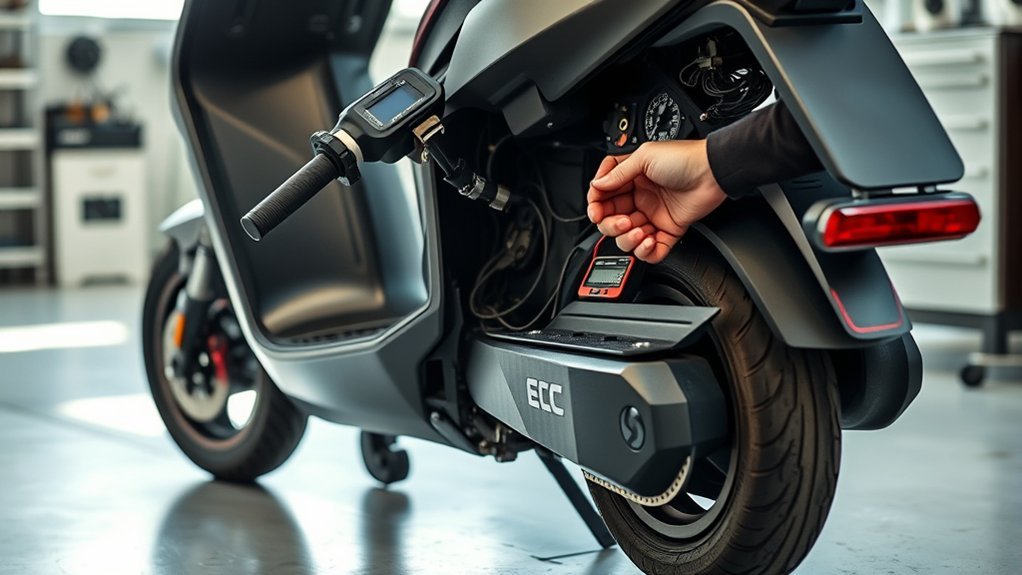
Last Updated on August 25, 2026 by Caleb Warren
An E7 error on an electric scooter indicates a critical communication fault or signal loss between the motor controller and peripheral components—most commonly the throttle, electronic brake sensor, or brushless motor Hall sensors. This error occurs when the main control board (ESC) stops receiving valid data over the serial communication line (UART) or detects an out-of-spec voltage signal from sensor lines, causing the firmware to cut motor power as a safety measure. Resolving it requires inspecting the wiring harness along the folding stem, cleaning oxidized pin connectors, and testing sensor return voltages with a digital multimeter.
Quick Answer
To fix an E7 error on an electric scooter, power down the system, unplug the main wiring harness at the stem and controller, and inspect for bent, burnt, or oxidized pins. Test the throttle signal wire (must read 0.8V to 4.2V DC) and motor Hall sensors (must toggle between 0V and 5V DC when spinning the wheel). Replace any damaged wiring or failed sensors, then reseat all waterproof connectors firmly.
Key Takeaways
- Core Cause: Broken signal wires inside the folding stem, oxidized waterproof connectors, or failing Hall effect sensors inside the throttle or motor.
- Brand Variance: On UART-based throttles (e.g., KingSong, generic LCDs), E7 indicates a communication timeout; on QS-S4/TF-100 displays, E-07 specifically designates a Motor/Hall Sensor Fault.
- Primary Diagnostic Tool: A digital multimeter set to DC Voltage is essential to verify the 5V reference line, the 0.8V–4.2V throttle output sweep, and the Hall sensor switching state.
- Safety First: Always disconnect the main battery pack before disconnecting or testing controller phase wires to prevent short circuits and capacitor arcing.
At a Glance
| Time Required | 20–45 Minutes |
| Difficulty | Intermediate (Requires Multimeter & Wire Inspection) |
| Tools Needed | Digital Multimeter, Hex/Allen Keys, Electrical Contact Cleaner, Heat Shrink Tubing, Soldering Iron |
| Cost | $0 (Cleaning/Reseating) to $25–$65 (Replacement Throttle or Controller) |
Disclosure: As an Amazon Associate I earn from qualifying purchases. Some links on this page are affiliate links, at no extra cost to you.
What E7 Means on Your Scooter
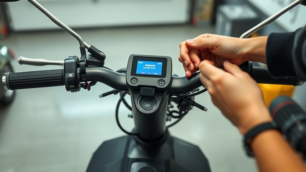
On electric scooters, error codes serve as built-in protection routines. When the firmware triggers an E7 code, the motor controller shuts off throttle input to prevent sudden acceleration, motor cogging, or electrical runaway. Because different manufacturers utilize distinct throttle protocols and display units, the exact subsystem flagged by E7 depends on your scooter’s hardware ecosystem:
| Display / Controller Platform | Specific Fault Indication | Primary Checkpoint |
|---|---|---|
| TF-100 / QS-S4 / LH-100 Displays | Motor Fault / BLDC Hall Sensor Signal Lost | Motor Phase & 5-Pin Hall Sensor Harness |
| Generic UART / Dualtron / Minimotors | RX/TX Serial Communication Timeout | Main Stem Cable Loom & Dashboard Plugs |
| Hiboy / Kugoo / Clone ESCs | Brake Cutoff Switch Stuck or Throttle Line Open | Brake Lever Sensor & Accelerator Potentiometer |
Regardless of brand, an E7 error is an electrical signal integrity issue, not a dead battery pack. It indicates that electricity is reaching the display, but critical data packets or analog voltage signals are failing to reach the Electronic Speed Controller (ESC).
Check the Scooter’s Wiring First
Over 80% of communication faults on folding electric scooters stem from physical wire degradation. The wiring loom passes directly through the folding stem and steering neck, subjecting internal copper strands to repetitive bending, friction, and tension every time the scooter is folded or steered.
- Inspect the Folding Joint: Examine the rubber grommet where the main cable harness enters the deck. Look for cracked exterior insulation, pinched wires, or exposed copper.
- Check Round Waterproof Connectors (Julet/Higo Plugs): Disconnect each quick-release plug on the handlebars and stem. Inspect for bent brass pins, receded terminals, or moisture ingress.
- Perform a Wiggle Test: With the scooter powered on and securely propped on a stand, gently flex the cable loom near the steering joint while observing the display. If the E7 code flashes or disappears intermittently, an internal conductor is fractured.
- Clean Terminals: Spray electronic contact cleaner into male and female plugs to dissolve oxidation and displace trapped water.
Pro Tip: When reconnecting waterproof circular plugs, align the molded internal indexing arrows before pushing the connectors together. Forcing misaligned pins will bend the 5V reference pin, permanently triggering an E7 or E10 code.
Test the Throttle and Brake Sensors
Electric scooter throttles and electronic brake levers use Hall effect sensors that convert magnetic fields into linear DC voltage. If the throttle sensor sends a voltage outside normal operating parameters (below 0.5V or above 4.8V), the controller registers an open circuit or short, throwing an E7 code.
Note: Standard 3-wire throttle harnesses follow a uniform color standard: Red (+5V DC supply), Black (Ground), and Green/Blue (Variable Signal Output).
- Set Your Multimeter: Switch the meter to 20V DC mode.
- Verify 5V Supply Rail: Back-probe the connector between the Red (+5V) and Black (GND) wires while the scooter is powered on. You should read a steady 4.8V to 5.2V DC from the controller.
- Test the Signal Sweep: Keep the black meter probe on Ground and place the red probe on the Green/Blue signal wire.
- Resting Position: The meter should read approximately 0.8V to 1.0V DC.
- Full Throttle: Slowly press the accelerator lever; voltage must rise smoothly without spikes to 3.6V–4.2V DC.
- Failure Condition: A reading of 0V, a constant 5V, or erratic jumping indicates a cracked magnet, failed Hall sensor element, or severed signal wire.
- Check Brake Inhibit Switches: Electronic brake levers send a cut-off signal to the controller. If the brake sensor’s internal return spring is jammed, the controller will suppress throttle communication. Measure continuity across the two brake signal pins; continuity should only exist when the brake lever is pulled.
Reset the Scooter and Reseat Connectors
A full electrical power cycle discharges stored energy from the ESC’s filtering capacitors, resetting the microcontroller’s temporary error register.
Power Down Fully
Turn the scooter off using the power button or key ignition. If your scooter has an accessible external battery or an easily removable deck plate, disconnect the main XT60/XT90 power connector from the battery pack. Let the scooter sit unpowered for 5 to 10 minutes. This allows the high-voltage electrolytic capacitors inside the ESC to fully drain, clearing volatile RAM faults.
Warning: Never short battery terminals or disconnect plugs under active motor load. Lithium-ion scooter batteries operate between 36V and 72V DC and can produce dangerous sparks or arc flashes if misconnected.
Reseat All Connectors
While the power is disconnected, trace every wiring line entering the controller inside the deck:
- Unplug the main 5-to-8-pin dashboard communication cable.
- Inspect internal terminals for burnt smells, black arcing marks, or loose crimps.
- Re-plug every connector until the locking tabs or threaded waterproof collars click firmly into place.
Recheck After Reset
Reconnect the main battery, power on the display, and check if the E7 code has cleared. If the error clears on the stand but re-appears during road vibration, the root cause is an intermittent terminal contact rather than a blown circuit board.
Test the Motor and Hall Sensor Wires
If your scooter uses a display platform where E7 corresponds to a motor fault, the issue lies in the 3 brushless motor phase wires (heavy Blue, Green, Yellow leads) or the 5-pin low-voltage Hall sensor harness (Red, Black, Yellow, Green, Blue leads).
“Brushless DC hub motors rely on three internal Hall effect sensors spaced at 60° or 120° intervals to communicate rotor position to the controller. A single broken signal lead prevents ESC commutation and immediately triggers an E7 code.”
| Test Stage | Multimeter Setting | Expected Result | Defect Sign |
|---|---|---|---|
| Phase Wire Resistance | Resistance (200Ω) | Equal resistance (< 0.5Ω) across Blue–Green, Green–Yellow, and Blue–Yellow pairs. | Open line (OL / ∞) indicates melted stator winding. |
| Hall Sensor Supply | 20V DC | Steady +5V DC across Red and Black Hall leads from the controller. | 0V reading indicates blown ESC 5V step-down regulator. |
| Hall Signal Switching | 20V DC | Voltage toggles cleanly between 0V and ~5V DC as the wheel is rotated slowly by hand. | Voltage stays stuck at 0V or 5V; blown Hall sensor board. |
Repair Loose Wires or Replace Faulty Parts
Once diagnostics identify the weak link, execute permanent hardware repairs rather than temporary tape patches:
- Solder Fractured Conductors: Strip broken wire ends by 5mm, slide marine-grade adhesive heat-shrink tubing over the wire, twist the copper conductors into a Western Union splice, and solder with 60/40 rosin-core solder. Seal with the heat shrink.
- Replace Throttle Assembly: If the throttle sensor fails the 0.8V–4.2V sweep test, replace the throttle module. They are sealed units and cannot be reliably serviced internally.
- Replace Motor Hall Sensors: If one phase fails the 0V/5V toggle test, open the hub motor side cover and desolder the damaged bipolar Hall sensor chip (typically type 41F / SS41F). Solder a matching replacement using thermally conductive potting adhesive.
Check the Controller for E7 Faults
If all wiring harnesses, throttles, and Hall sensors test within nominal voltage ranges, the E7 error originates inside the Electronic Speed Controller (ESC) itself. Open the controller deck bay and conduct a visual and component-level inspection:
- MOSFET Short-Circuit Test: Set your multimeter to Diode/Continuity mode. Place one probe on the main negative battery input lead and probe each of the three motor phase outputs. A continuous beep indicates a blown power MOSFET transistor.
- Check for Burnt Traces or Odor: Look for discolored PCB board traces, bubbling conformal coating, or scorched electrolytic capacitors.
- Evaluate 5V Regulator: If the controller fails to output 5V DC to the throttle and hall sensor harness, its internal linear step-down regulator (e.g., LM7805 or buck converter) has failed.
Because modern scooter controllers are potted in silicone or epoxy for weatherproofing, repairing surface-mount board components is rarely practical. Replacing the ESC with an OEM or compatible programmed controller is the most reliable remedy.
Prevent E7 Errors on Future Rides
Proactive maintenance prevents mechanical wear from escalating into electrical signal failures:
- Install Spiral Cable Wrap: Wrap exposed wiring looms at the folding stem and handlebar base with protective spiral cable wrap to disperse friction.
- Dielectric Grease on Terminals: Apply a small amount of non-conductive dielectric grease into all Julet/Higo connector pins to block water entry and eliminate pin fretting corrosion.
- Avoid Full-Lock Cable Strain: Ensure cables have sufficient slack when the handlebars are turned completely to the left and right stops.
- Keep Deck Seals Maintained: Inspect the rubber deck perimeter gasket quarterly to ensure moisture cannot enter the battery and controller compartment during wet rides.
Frequently Asked Questions
How to Fix E7 Code on Electric Scooter?
To fix an E7 code, turn off the scooter and inspect the main wiring harness along the steering stem for pinched or severed wires. Unplug and reseat the dashboard, throttle, and controller connectors, checking for bent or corroded pins. Use a multimeter to verify that the throttle produces 0.8V to 4.2V DC and that motor Hall sensors toggle 0V to 5V DC. Replace any damaged sensor or wiring loom.
How to Correct an E7 Error?
You correct an E7 error by systematically isolating the signal break. Start by checking the brake cutoff sensors to ensure a lever switch is not stuck closed. Next, inspect the UART data cables connecting the display to the controller. If the wiring harness is intact and all plugs are clean, test the controller MOSFETs and replace the ESC if internal circuitry has shorted.
How Do I Reset an Electric Scooter?
To reset an electric scooter, power off the device, disconnect the main battery pack via its XT60 or primary connector, and hold down the power button for 15 seconds to drain residual energy from controller capacitors. Leave the scooter disconnected for 10 minutes, reconnect the battery, and power the unit back on to clear temporary software latch states.
How to Fix E7 Error on Electric Scooter Reddit?
Community fixes on Reddit and DIY forums emphasize checking the quick-disconnect cable located 4–6 inches below the handlebars on popular commuter models. This plug often wiggles loose during riding or collects condensation. Unplugging it, spraying contact cleaner, and firmly reseating the connector until fully locked resolves the vast majority of crowd-reported E7 codes.
Conclusion
An E7 error code on your electric scooter is a protective signal cutoff rather than a catastrophic battery breakdown. In most scenarios, the issue traces back to physical wire fatigue at the folding hinge, an oxidized quick-release connector pin, or a failing Hall effect sensor in the throttle or hub motor. By methodically checking physical connections, measuring operational DC voltages with a multimeter, and inspecting controller health, you can pinpoint the broken communication link and restore smooth, responsive acceleration.
Sources
- ScooterHacking.org — Electric scooter firmware protocols and hardware error diagnostic documentation.
- Texas Instruments — Technical Application Report: Hall-Effect Sensor Applications in Brushless DC Motors and Electronic Throttles.
- Mikrocontroller.net — BLDC Motor Controller Commutation and UART Serial Protocol Analysis.
