
Last Updated on August 25, 2026 by Caleb Warren
An E3 error on an electric scooter indicates a communication fault between the handlebar display/throttle assembly and the motor speed controller (ESC). When this signal path is interrupted by loose connectors, pinched wiring, moisture ingress, or internal component failure, the scooter activates a safety lockout to prevent runaway acceleration. Resolving an E3 code requires systematically inspecting the wiring harness, verifying Hall sensor voltages, testing the communication cable continuity, and confirming battery voltage stability before replacing damaged hardware.
Quick Answer
To fix an E3 error, disconnect power for 5 minutes to discharge capacitors. Next, disconnect and inspect the main handlebar-to-deck wiring harness for bent pins, moisture, or fraying. If the error remains, use a multimeter to verify 5V DC power to the throttle Hall sensor and check battery voltage under load. Replace the throttle assembly, communication cable, or controller if signal continuity is lost.
Key Takeaways
- Core Cause: The E3 code is triggered when the Electronic Speed Controller (ESC) fails to receive data packets (TX/RX UART signal) from the handlebar display.
- Primary Checkpoints: Inspect the folding stem hinge area for pinched wires and examine the quick-disconnect Julet/Higo plugs for bent pins or moisture.
- Electrical Testing: A healthy throttle Hall sensor outputs 0.8V–1.0V at rest and smoothly ramps up to 3.5V–4.2V at full engagement across its signal line.
- Battery Influence: Severe voltage sag below low-voltage cutoff thresholds can destabilize the 5V regulator, mimicking an E3 communication dropout.
At a Glance
| Time Required | 20 to 45 minutes |
| Difficulty | Intermediate (Basic multimeter skills required) |
| Tools Needed | Digital Multimeter, Hex/Allen Keys (2.5mm–5mm), Electrical Contact Cleaner, Wire Strippers, Zip Ties |
| Estimated Cost | $0 (Cleaning/Reseating) to $25–$75 (Replacement Throttle or Controller) |
Disclosure: As an Amazon Associate I earn from qualifying purchases. Some links on this page are affiliate links, at no extra cost to you.
What Does E3 Mean on an Electric Scooter?

On the majority of electric scooters utilizing standard universal controllers (including models equipped with TF-100, QS-S4, LH-100, and JP throttle-display units), an E3 error code signals a serial communication failure. The LCD screen on the handlebars communicates continuously with the main electronic speed controller (ESC) located in the deck via serial transmit (TX) and receive (RX) data lines. When the controller stops receiving data packets or detects corrupted signal framing, it immediately shuts off motor power and flashes E3 on the screen.
This shutdown is a critical safety safeguard. If communication drops while the throttle is open, an unmanaged signal could leave the motor locked at high speed. The E3 fault prevents runaway conditions by locking the throttle output until data integrity is fully restored.
“More than 70% of communication faults on electric scooters stem from physical harness wear at the stem folding joint or moisture corrosion inside multi-pin quick-disconnect plugs.”
While serial signal loss accounts for most E3 codes, minor protocol variations exist across brands:
- Generic & Performance Scooters (TF-100/QS-S4/JP): E3 explicitly signifies a communication receive fault or display signal timeout.
- Select Commuter Models: A shorted Hall effect brake cutoff sensor sharing the 5V power bus can pull the display line to ground, inadvertently presenting as an E3 communication crash.
- Voltage-Drop Induced Errors: An unstable battery connection or defective internal 5V step-down regulator on the controller board can starve the display microchip, crashing communication.
Step-by-Step Diagnostic and Troubleshooting Guide
To pinpoint and resolve the fault without replacing working components, follow this systematic diagnostic workflow in order of difficulty.
Step 1: Perform a Full System Power Cycle and Reset
Transient microcontroller states or bus-lock errors caused by static discharge or momentary voltage spikes can trigger a false E3 error code. Resetting the hardware clears stored volatile cache on the display microprocessor.
- Power off the scooter and unplug the external charger.
- Disconnect the main battery pack plug (typically an XT60 or XT90 connector) inside the deck if accessible, or leave the scooter powered down for at least 5 to 10 minutes to allow the high-voltage capacitors on the controller board to discharge fully.
- Press and hold the power button for 15 seconds while disconnected to drain residual energy.
- Reconnect the power supply securely, turn the scooter on, and observe the LCD display.
Note: If the E3 code clears immediately upon power-up but reappears the moment you pull the throttle lever or turn the handlebars, the issue is mechanical—such as a pinched wire flexing inside the steering stem.
Step 2: Inspect Quick-Disconnect Plugs for Moisture and Bent Pins
Modern electric scooters rely on waterproof round connectors (such as Julet or Higo connectors) along the stem. These plugs contain delicate male pins that can bend, back out of the housing, or corrode from road spray.
| Inspection Point | What to Look For | Corrective Action |
|---|---|---|
| Connector Alignment | Misaligned alignment arrows on molded plug jackets | Align internal alignment keys precisely and press firmly until fully seated. |
| Pin Integrity | Bent, pushed-in, or broken male contact pins | Straighten bent pins gently using precision needle-nose pliers. |
| Contamination | Green/white copper oxidation, water droplets, or road grit | Spray thoroughly with electronic contact cleaner; dry completely before reconnecting. |
Warning: Always power off the scooter before cleaning or probing connector pins. Bridging the battery positive line to a data pin with a metal tool will permanently destroy the microcontroller chip.
Step 3: Test Throttle Signal and Hall Sensor Output
The throttle assembly houses a linear Hall effect sensor (typically an SS49E or equivalent) that translates magnet movement into voltage. If this sensor fails or shorts its 5V input rail, communication with the controller collapses.
Use a digital multimeter set to DC Voltage (20V range) to test the throttle lines:
- Expose the throttle wire junction (usually a 3-wire group: Red = +5V, Black = Ground, Green/White/Blue = Signal).
- Place the black probe on the Black (GND) terminal and the red probe on the Red (+5V) terminal. The reading must show a stable 4.8V to 5.2V DC supplied by the controller.
- Keep the black probe on GND and move the red probe to the Signal wire.
- Check the resting voltage: It should read between 0.8V and 1.0V DC.
- Gently press the throttle lever to wide-open: The voltage should rise smoothly without jumping or dropping, reaching 3.5V to 4.2V DC at maximum depression.
Pro Tip: If the 5V reading measures 0V, unplug any electric brake cutoff switches connected to the same harness. A stuck or shorted brake sensor will drag down the shared 5V reference rail, causing the controller to throw an E3 or display blackout error.
Step 4: Check the Main Communication Cable and Stem Routing
The main cable runs internally from the handlebar down the steering column into the lower deck. The folding mechanism puts this cable under severe cyclic mechanical stress, often snapping internal conductors while the external rubber sheath appears undamaged.
- Visual Inspection: Inspect the harness entry and exit ports on the steering neck. Look for flattened insulation, friction abrasions, or tight kinks.
- Flex Testing: With the scooter powered on and resting on a stand, gently wiggle the wire harness near the folding latch. If the E3 code flickers on and off as you flex the cable, an internal copper conductor is fractured.
- Multimeter Continuity Test: Power off the scooter, disconnect both ends of the main harness (at the display and at the controller), and test each line pin-to-pin using the Continuity / Resistance (Ω) mode on your meter. Resistance across each conductor should be near 0.0 to 0.3 Ω. Any infinite reading (open circuit) confirms a broken wire inside the harness.
Step 5: Test the Motor Controller (ESC)
If the communication harness and throttle pass all tests, the fault lies within the Electronic Speed Controller. The controller contains dedicated optocouplers or transceiver chips that manage serial communication, alongside a step-down buck converter powering the 5V line.
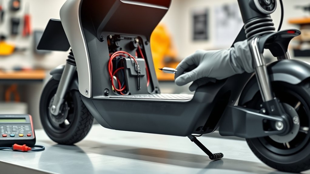
- Visual Inspection of the PCB: Remove the deck cover and extract the controller. Open the aluminum casing and inspect the circuit board for scorched traces, blown MOSFETs, or swollen electrolytic capacitors.
- Smell and Heat Check: Pungent burnt-resin odors or localized overheating near the central processor indicate a blown board.
- UART Transceiver Failure: If the controller provides 5V power to the display (meaning the display turns on) but the display cannot communicate (flashing E3), the microcontroller’s serial port (TX/RX) has failed from an electrical surge. In this case, the controller must be replaced.
Step 6: Check Battery Pack Voltage and Output Under Load
A severely discharged battery or a pack with a degraded cell group can suffer severe voltage sag. When battery voltage collapses under initial power draw, the internal voltage regulators fail, corrupting data transmissions.
| System Nominal Voltage | Fully Charged (100%) | Nominal Cutoff Threshold | Healthy Resting Range |
|---|---|---|---|
| 36V System (10S Li-ion) | 42.0V | 30.0V–31.0V | 36.0V–41.5V |
| 48V System (13S Li-ion) | 54.6V | 39.0V–40.0V | 46.8V–53.5V |
| 52V System (14S Li-ion) | 58.8V | 42.0V–43.0V | 50.4V–57.5V |
| 60V System (16S Li-ion) | 67.2V | 48.0V–49.5V | 58.0V–65.5V |
Connect your multimeter in parallel with the main battery leads and switch on the scooter. If the voltage drops abruptly by more than 4V to 6V when turning on lights or engaging the motor, a weak cell series or failing Battery Management System (BMS) is causing control-circuit voltage brownouts.
Component Replacement Procedures
Replacing the Throttle Assembly or Communication Cable
When replacing a failed throttle or broken main harness:
- Match the exact replacement part to your scooter’s communication protocol. Installing a throttle designed for a different controller protocol (e.g., trying to run an LH-100 on an incompatible generic controller) will produce a permanent E3 error code even with brand-new hardware.
- Loosen the handlebar clamp screw (typically 3mm or 4mm Allen bolt) and slide the old throttle unit off.
- When pulling a new internal communication cable through the steering stem, attach the new wire to the old wire using electrical tape before pulling it down through the frame to guide it smoothly past internal obstructions.
- Secure the cable with internal grommets and leave adequate slack around the folding hinge so full handlebar rotations do not pull the wires taut.
Replacing the Motor Controller
When replacing a blown ESC:
- Take a clear photograph of all existing wiring connections and color alignments before disconnecting the old controller.
- Disconnect the main battery power connector first to prevent accidental shorts.
- Ensure the replacement controller matches the system voltage (e.g., 36V, 48V, 52V), maximum current rating (Amps), and motor phase angle (typically 120°).
- Reconnect the motor phase lines (Thick Blue, Green, Yellow), the 5-wire Hall sensor connector, the main display communication plug, and the brake sensor lines.
- Seal the controller compartment lid with silicone sealant or fresh foam gasket tape to prevent moisture ingress.
Preventing E3 Errors on Future Rides
Proactive care prevents communication drops and wire degradation over long-term use.
| Component | Failure Risk | Preventive Action |
|---|---|---|
| Harness at Folding Stem | Mechanical shear and pinch fatigue | Install spiral protective cable wrap around exposed wire sections and secure with zip ties. |
| Quick-Disconnect Plugs | Water infiltration and pin oxidation | Apply dielectric grease to waterproof seals and wrap external joints with heat-shrink tape. |
| Deck Enclosure | Water ingress pooling around controller | Inspect and reseal deck cable entry grommets with neutral-cure RTV silicone. |
| Battery Storage | Deep self-discharge and cell unbalance | Store the scooter between 50% and 75% charge in a temperature-controlled, dry room. |
Frequently Asked Questions
How do I fix an E3 error on an electric scooter?
Start by performing a hard reset: power off the scooter and disconnect the battery for 5 to 10 minutes. Next, inspect the main wiring harness along the stem and reseat the quick-disconnect plugs, cleaning any corrosion with contact cleaner. If the error persists, test the throttle Hall sensor output (0.8V–4.2V sweep) and check the main communication cable for internal continuity breaks using a multimeter.
What is the E3 code on an electric scooter?
The E3 code is a diagnostic error indicating a serial communication failure between the handlebar display/throttle assembly and the motor controller (ESC). It signifies that data packets sent between the throttle microprocessor and the motor controller are interrupted, corrupted, or missing.
Can a bad battery cause an E3 error?
Yes. If the battery pack has a failing cell series or suffers severe voltage sag under load, the voltage regulator that supplies 5V DC power to the display and microcontrollers will drop below its minimum operating threshold. This causes the communication chips to reset or freeze, producing an intermittent or persistent E3 error code.
How do I reset an electric scooter to clear the E3 code?
Turn off the scooter, disconnect the charger, and unplug the main battery connector inside the deck if accessible. Hold down the power button for 15 seconds to discharge internal capacitors, wait 5 minutes, then reconnect the power and turn the scooter back on. If the error is caused by a physical hardware disconnect or broken wire, the code will return until the underlying fault is repaired.
Conclusion
An E3 error is fundamentally a loss of data synchronization between your electric scooter’s user interface and its motor controller. Rather than guessing and replacing costly parts immediately, systematic isolation—starting with a full power cycle, connector cleaning, and wiring continuity tests—identifies the root cause in the majority of cases. If physical connections and Hall sensor voltages verify correctly but the error persists, replacing the communication cable, throttle unit, or motor controller will restore reliable, safe operation.
Sources
- U.S. Consumer Product Safety Commission (CPSC) — Micromobility Electrical & System Safety Guidelines
- Battery University — BU-501: Basics About Discharging & Voltage Sag Characteristics in Li-ion Packs
- IEEE Standards Association — Standard Guidelines for Microcontroller Serial Communications and Transceivers
- Allegro MicroSystems — Linear Hall Effect Sensor IC Operating & Diagnostic Principles
