

Last Updated on July 28, 2026 by Daniel Globe
Automatic welding is a high-precision manufacturing process that utilizes motorized machinery, robotics, and computerized controls to perform welds with minimal manual intervention. Central to the success of any automated system is joint travel—the controlled speed, path, and directional movement of the welding head or workpiece along the joint seam. Properly managing joint travel ensures optimal heat input, uniform bead appearance, and structural joint integrity across automotive, aerospace, and heavy industrial applications.
Quick Answer
Joint travel in automatic welding refers to the mechanized movement and travel speed of the welding torch relative to the weld joint. It directly dictates heat input, penetration depth, and bead geometry. Precise joint travel control prevents common defects such as undercutting, burn-through, and incomplete fusion, ensuring consistent, high-strength welds.
Key Takeaways
- Heat Input Control: Travel speed is the primary variable controlling heat input per unit length; moving too fast reduces penetration, while moving too slow risks warping or burn-through.
- Motion Systems: Automatic joint travel relies on linear actuators, rotary positioners, gantry carriages, or 6-axis robotic arms.
- Real-Time Adaptation: Modern automated systems incorporate laser vision and Through-Arc Seam Tracking (TAST) to correct path deviations automatically.
- Quality Standards: Consistent travel speed yields uniform bead width, minimal spatter, and repeatable mechanical properties meeting strict industrial standards.
Disclosure: As an Amazon Associate I earn from qualifying purchases. Some links on this page are affiliate links, at no extra cost to you.
The Importance of Joint Travel in Automatic Welding
Automatic welding systems have revolutionized industrial fabrication by replacing manual torch manipulation with programmable mechanized motion. Whether utilizing Gas Metal Arc Welding (GMAW), Gas Tungsten Arc Welding (GTAW), or Submerged Arc Welding (SAW), controlling the rate and accuracy of joint travel is critical to achieving defect-free welds.
Even Heat Distribution & Thermal Dynamics
Proper joint travel maintains a steady thermal equilibrium along the weld seam. Because electrical arc energy is continuously deposited into the base metal, any velocity fluctuation alters local temperature profiles. Uniform motion ensures that the molten weld pool freezes evenly, preventing localized stress concentrations and microstructural inconsistencies.
Heat Input Formula in Automatic Welding
In automated welding specifications, heat input ($H$) is calculated using the voltage ($V$), amperage ($I$), and travel speed ($S$):
Heat Input Formula:
$$H = \frac{V \times I \times 60}{S \times 1000}$$
Where $H$ is Heat Input (kJ/mm), $V$ is Arc Voltage (volts), $I$ is Welding Current (amps), and $S$ is Travel Speed (mm/min).
Because travel speed ($S$) sits in the denominator, small adjustments to motion velocity dramatically alter thermal energy density delivered to the steel or aluminum plate.
Impact on Penetration and Defect Rates
Optimizing joint travel speed balances arc force and puddle behavior:
- Excessive Travel Speed: The arc moves faster than the thermal conduction rate, leading to shallow penetration, lack of sidewall fusion, bead humping, and edge undercutting.
- Insufficient Travel Speed: The weld pool flows ahead of the arc, cushioning the force of the arc stream. This results in excessive heat accumulation, wide distortion zones, top-heavy bead reinforcement, or catastrophic burn-through on thin-gauge materials.
Warning: Operating at incorrect travel speeds can produce visual welds that appear acceptable on the surface but suffer from internal lack-of-fusion (LOF) defects detectable only through non-destructive testing (NDT) such as radiography or ultrasonic inspection.
Types of Joint Travel Mechanisms in Automatic Welding
Automated joint travel is generated using precision mechanical motion platforms controlled by Programmable Logic Controllers (PLCs) or Computer Numerical Control (CNC) software.

Products Worth Considering

Smooth Rotation: VEVOR rotary welding positioner boasts 20W high quality motor that runs at 1-12 rpm low speed for stable operation. With a load capacity of up to 11lbs/5 Kg (vertical) or 22lbs/10 Kg (horizontal), it offers excellent stability and supports efficient, precise welding.

Stable and Powerful Motor: VEVOR’s rotary welding positioner is equipped with a high-quality 120W motor, providing a low-speed range of 0.5-6 rpm. This ensures stable and smooth operation for precise welding tasks. The positioner offers excellent stability with a vertical load capacity of up to 55 lbs (25 kg) and a horizontal load capacity of 110 lbs (50 kg).

【🎯PRECISION CLAMPING】Equipped with a 2.56" 3-jaw lathe chuck, this automatic welding turntable securely holds round workpieces from 0.08" to 2.28", eliminating manual adjustments and providing steady hands-free operation for flawless MIG/TIG seams.
1. Linear Motion Actuators & Side-Beam Carriages
For long straight seams—such as structural I-beams, tank seams, or pipe manufacturing—linear carriages move the welding head along a fixed rigid track. Powered by electric stepper or servo motors, linear actuators supply smooth, non-pulsating motion over extended lengths.
2. Rotary Positioners & Turning Rolls
When joining cylindrical assemblies like pressure vessels, pipes, or shafts, the welding torch often remains stationary while a rotary positioner rotates the workpiece underneath. Speed control must be calibrated to linear peripheral velocity (inches or millimeters per minute) rather than strict revolutions per minute (RPM) to maintain consistent bead sizing across varying pipe diameters.
3. Multi-Axis Robotic Arms & Gantry Systems
Modern industrial robotics utilize 6-axis articulated arms operating on overhead linear gantries. These combined systems maintain complex torch orientation, torch angle (push/drag), contact-tip-to-work distance (CTWD), and precise joint travel along 3D contoured weld paths.
Factors Affecting Joint Travel in Automatic Welding
| Factor | Impact on Joint Travel Dynamics |
|---|---|
| Joint Geometry | Root opening, bevel angle, and backing bars dictate required fill volume. Deep V-grooves require slower travel or weaving, whereas square butt joints allow faster speeds. |
| Material Thickness | Thicker plates dissipate heat rapidly and require higher energy input (slower travel speed or preheating), whereas sheet metal demands elevated travel speeds to prevent burn-through. |
| Welding Position | Flat (1G/1F) positions allow maximum travel speeds. Vertical (3G) or overhead (4G) positions require modified travel speeds and weave parameters to fight gravitational sag. |
| Welding Process | Submerged Arc Welding (SAW) achieves high travel speeds due to massive deposition rates. GTAW (TIG) requires slower, controlled travel speeds for high-purity thermal transfer. |
| Joint Fit-Up & Alignment | Gaps or root face variations require adaptive speed adjustments; inconsistent fit-up forces travel speed reductions to avoid burn-through. |
Products Worth Considering

SPECIFICATION: 49PCS TIG Torch Accessories kit (consumables).

Extra-Long 13-FT Air Hose: Instead of moving the Argon welding cylinder tank all around, ARCCAPTAIN TIG Torch equipped with an extra-long 13-FT air hose and cables brings enormous convenience for distance welding. Meanwhile(furthermore), the cables are made of durable rubber hose with nylon over-braid, super-light, this innovative design makes the TIG welding torch keep(super) flexible under any circumstances.
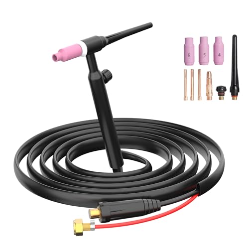
TIG Gun Design:Gas hose and power cable is separated, used for independent connection with the gas outlet of the welding machine or directly connected with the argon flow-meter.
Advantages of Proper Joint Travel Optimization
Accurately controlling joint travel velocity produces substantial financial and technical benefits in high-volume production environment:
- Superior Weld Consistency: Mechanized travel eliminates human fatigue, tremors, and uneven pace, delivering identical bead profiles across thousands of production cycles.
- Higher Deposition Efficiency: Matching travel speed perfectly to wire feed speed maximizes metal deposition without excessive reinforcement or spatter losses.
- Reduced Post-Weld Rework: Uniform heat distribution minimizes angular distortion and plate warping, drastically reducing post-weld straightening and grinding costs.
- Optimized Cycle Times: Pushing travel speed to the maximum allowable limit without compromising fusion shortens fabrication lead times.
Challenges and Common Issues with Joint Travel

Implementing continuous automated joint travel introduces specific technical hurdles that operators and automation engineers must address:
Mechanical Backlash and Velocity Variations
Worn drive gears, slipping drive rolls, or friction along guide tracks cause microscopic fluctuations in travel speed. These momentary stalls cause localized heat buildup, creating unsightly wide spots or burning holes through thin metal.
Thermal Distortion and Path Drift
As welding progresses, intense localized heating causes the base metal to expand and pull. If joint travel is pre-programmed along a rigid straight line, the actual physical joint may warp away from the torch path, resulting in off-seam welds.
Pro Tip: Utilize closed-loop encoder feedback on motor drives to maintain velocity accuracy within $\pm 1\%$ under varying torch payloads and cable-drag resistance.
Techniques for Optimizing Joint Travel in Automatic Welding
Products Worth Considering

ROTARY LASER LEVEL: This Johnson Self Leveling Kit is ideal for one-person application in various indoor and outdoor jobs. Perfect for small jobsites; this rotary tool self-levels in the horizontal plane and levels manually in the vertical plane.

❤️【𝐀𝐝𝐯𝐚𝐧𝐭𝐚𝐠𝐞】Local inventory in the U.S., delivered directly to your doorstep with no extra fees. 10 swing modes, capable of easily handling metal welding below 8mm, with sufficient melting depth and adjustable width; It can efficiently overcome the difficulties of complex joints, curved welds, and large gap processing
1. Closed-Loop Adaptive Seam Tracking
Modern automated cells incorporate real-time sensing technologies to maintain torch alignment along the joint:
- Through-Arc Seam Tracking (TAST): Measures electrical current fluctuations caused by stickout distance changes as the torch weaves across the joint, dynamically adjusting horizontal and vertical positioning.
- Optical Laser Vision Systems: Projects a laser line ahead of the welding arc. A camera measures joint gap, bevel geometry, and alignment in real time, automatically correcting torch position and travel speed.
2. CAD/CAM Integration and Predictive FEA
Engineers simulate thermal dissipation and joint travel speed using Finite Element Analysis (FEA) software before striking an arc. Computer-Aided Manufacturing (CAM) programs automatically generate velocity curves that slow down around tight radii and accelerate along straight sections.
The Future of Joint Travel in Automatic Welding
Emerging developments in industrial automation are shaping the next generation of joint motion control:
- Artificial Intelligence & Neural Networks: AI algorithms evaluate real-time puddle geometry from high-speed CMOS cameras, tweaking joint travel speed milliseconds before defects form.
- IoT Connected Power Sources: Cloud-connected welding systems sync travel carriage encoders directly with inverter power supplies, dynamically re-calculating heat input output instantaneously.
- Collaborative Cobot Motion: Lightweight cobots feature intuitive hand-guiding interfaces that allow operators to teach complex joint paths and speed points without formal CNC coding knowledge.
Frequently Asked Questions
What is joint travel in automatic welding?
Joint travel in automatic welding refers to the controlled mechanical velocity and path traversed by the welding torch relative to the workpiece joint seam. It controls the rate of energy and filler metal deposition into the weld joint.
What provides the joint travel in automatic welding systems?
Joint travel is powered by motorized mechanical equipment, including linear side-beam carriages, motorized rotary positioners, CNC gantry systems, or multi-axis industrial robotic arms equipped with precision servo motors and encoder feedback.
Why is travel speed critical in automatic welding?
Travel speed directly controls thermal heat input ($kJ/mm$). Moving too fast causes shallow penetration, lack of fusion, and undercutting. Moving too slow results in excessive heat accumulation, plate distortion, coarse grain structures, or burn-through.
What are the benefits of automated joint travel over manual welding?
Automated joint travel provides superior weld consistency, faster travel speeds, lower defect rates, reduced operator fatigue, and exact repeatability across large-scale industrial manufacturing runs.
Sources
- American Welding Society (AWS) — Welding Inspection Handbook & Technical Standards
- Lincoln Electric — Robotic Automation & Motion Control Systems Guidelines
- Machine Design — Linear Actuator Motion Controls in Industrial Systems
- Miller Electric — Automated MIG/TIG Heat Input Principles & Calculations
